TM-9-2320-209-20-3-1 - Page 729 of 830
TM 9-2320-209-20-3-1
1.
2.
3.
GO
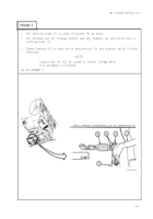
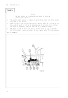
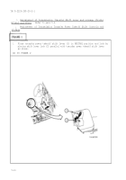
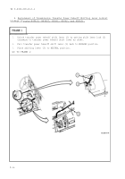
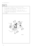
Place control rod (1) under truck as shown and aline holes in clevis (2) with
upper hole in shift control lever (3).
Put straight headed pin (4) through clevis (2).
Using needle nose pliers, put cotter pin (5) through hole in straight headed
pin (4) and spread ends.
TO FRAME 5
9-19
Back to Top

