TM-9-2320-209-20-3-4 - Page 136 of 410
TM 9-2320-209-20-3-4
b. Replacement and Adjustment.
FRAME 1
1.
2.
3.
4.
5.
6.
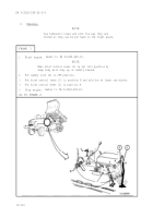
Put clevis (1) on lever (2) and put clevis pin (3) through holes in clevis and
lever.
Put cotter pin (4) through hole in clevis pin (3) and using pliers, bend open
ends of cotter pin.
Put rod assembly (5) through hole in frame crossmember (6) as shown. Turn
rod assembly so it is in position shown and put clevis (7) on lever (8).
Put clevis pin (9) through holes in clevis (7) and lever (8).
Put cotter pin (10) through hole in clevis pin (9) and using pliers, bend open
ends of cotter pin.
Push lever (2) as far forward as it will go.
GO TO FRAME 2
19-123
Back to Top


