TM-9-2320-260-34-1 - Page 164 of 657
TM 9-2320-260-34-1
3-33. FRONT GEAR COVER MAINTENANCE
THIS TASK COVERS:
a. Removal
c. Cleaning and Inspection
b. Disassembly
d. Assembly
INITIAL SETUP
APPLICABLE MODELS
All
TOOLS
General mechanic’s tool kit
(Appendix B, Item 1)
Bushing installer (Appendix B, Item 91)
Soft-head hammer (Appendix B, Item 47)
Outside micrometer (Appendix B, Item 8)
Two dowel pins (Appendix E, Figure E-6)
MATERIALS/PARTS
Seal (Appendix D, Item 407)
Packing (Appendix D, Item 303)
MATERIALS/PARTS (Contd)
Seal (Appendix D, Item 416)
Antiseize tape (Appendix C, Item 50)
REFERENCES (TM)
TM 9-2320-260-20
TM 9-2320-260-34P-1
EQUIPMENT CONDITION
l Crankshaft flange removed (para. 3-31).
l Accessory drive and pulley removed (para. 3-32).
l Fan bracket and hub removed
(TM 9-2320-260-20).
a. Removal
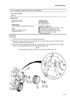
1. Remove four screws (6), lockwashers (5), and washers (4) from oil pan (2) and front gear cover (8).
Discard lockwashers (5).
NOTE
Screws attaching front gear cover are different lengths and must
be installed in their proper position. Tag screws for installation.
2. Remove fifteen screws (7), two screws (9), lockwashers (10), and washers (11) from front gear
cover (8). Discard lockwashers (10).
3. Install two 4 in. (102 mm) dowel
during removal.
4. Using softhead hammer, loosen
block (3). Discard gasket (1).
pins on each side of cylinder block (3) to support front gear cover (8)
and remove front gear cover (8) and gasket (1) from cylinder
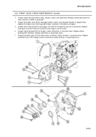
1. Remove seal (17) and sleeve bearing (16) from bore (14). Discard seal (17).
2. Remove sleeve bushing (23) and seal (24) from bore (25). Discard seal (24).
3. Remove two screws (18), camshaft cover (19), spacer plate (20), shim(s) (21), and packing (22) from
boss (13). Discard packing (22).
4. Remove pipe plugs (12) and (15) from front gear cover (8).
c. Cleaning and Inspection
1. For general cleaning instructions, refer to para. 2-8.
2. For general inspection instructions, refer to para 2-9.
3-112
Back to Top


