TM-9-2320-272-23-2 - Page 1041 of 1417
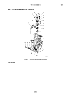
INSTALLATION (EXTERNAL BYPASS)
NOTE
If support was removed, perform Steps (1) and (2).
1.
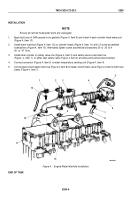
Install plug (Figure 4, Item 24) in support (Figure 4, Item 14).
2.
Install gasket (Figure 4, Item 15) and support (Figure 4, Item 14) on engine block (Figure 4, Item 16) with two
screws (Figure 4, Item 27).
3.
With housing (Figure 4, Item 10) upside down, install seal (Figure 4, Item 11), with cupped side down, until
seal is seated.
CAUTION
If seal is damaged, engine failure may result.
4.
Install thermostat (Figure 4, Item 12) into seal (Figure 4, Item 11) until thermostat (Figure 4, Item 12) seats
against housing (Figure 4, Item 10).
5.
Install gasket (Figure 4, Item 13) and housing (Figure 4, Item 10) on support (Figure 4, Item 14) with two screws
(Figure 4, Item 7).
6.
Install hose (Figure 4, Item 26) on housing (Figure 4, Item 10) and tighten clamp (Figure 4, Item 28).
7.
Install gasket (Figure 4, Item 9) and adapter (Figure 4, Item 8) on thermostat housing (Figure 4, Item 10) with
long screw (Figure 4, Item 3) and short screw (Figure 4, Item 6).
CAUTION
Ensure that drain valve on aftercooler is open or cooling system may overheat.
8.
Wrap threads of valve (Figure 4, Item 32) with antiseize tape and install in tee (Figure 4, Item 31), and install
tee on housing (Figure 4, Item 10).
9.
Install tube (Figure 4, Item 29), fitting (Figure 4, Item 2), and fitting (Figure 4, Item 30) on tee
(Figure
4,
Item
31).
10.
Install hose (Figure 4, Item 1) on valve (Figure 4, Item 32) and tighten clamp (Figure 4, Item 33).
11.
Install bracket (Figure 4, Item 25) on support (Figure 4, Item 14) with four screws (Figure 4, Item 23).
12.
Move alternator (Figure 4, Item 21) up and align bracket (Figure 4, Item 22) to support (Figure 4, Item 14) and
install two washers (Figure 4, Item 20) and screws (Figure 4, Item 19). Tighten screws 35 lb-ft (45
N·m).
13.
Tighten link screw (Figure 4, Item 18).
14.
Install hose (Figure 4, Item 4) on adapter (Figure 4, Item 8) and tighten clamp (Figure 4, Item 5).
TM 9-2320-272-23-2
0289
0289-8
Back to Top

