TM-9-2320-272-23-2 - Page 1049 of 1417
INSTALLATION
NOTE
Ensure all cylinder head water ports are unplugged.
1.
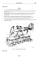
Apply light coat of GAA grease to six gaskets (Figure 4, Item 9) and install in each cylinder head water port
(Figure 4, Item 10).
2.
Install water manifold (Figure 4, Item 12) on cylinder heads (Figure 4, Item 11) with 12 screw assembled
lockwashers (Figure 4, Item 13). Alternately tighten screw assembled lockwashers 30
to
35
lb-ft
(41
to
47
N·m).
3.
Install ether cylinder on safety valve line (Figure 4, Item 3) and safety valve-to-atomizer line
(Figure
4,
Item
1) on ether start safety valve (Figure 4, Item 2) at same points where disconnected.
4.
Connect connector (Figure 4, Item 5) to water temperature sending unit (Figure 4, Item 4).
5.
Connect personnel heater inlet hose (Figure 4, Item 8) to heater shutoff drain valve (Figure 4, Item 6) with hose
clamp (Figure 4, Item 7).
1
2
3
4
5
6
7
8
9
10
11
12
13
M9816DAA
Figure 4.
Engine Water Manifold Installation.
END OF TASK
TM 9-2320-272-23-2
0290
0290-6
Back to Top


