TM-9-2320-272-23-2 - Page 1048 of 1417
ASSEMBLY
1.
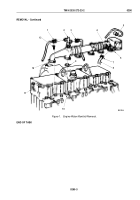
Wrap male threaded ends of water temperature sending unit (Figure 3, Item 7) and heater shutoff drain valve
(Figure 3, Item 6) with antiseize tape and install in front water manifold section (Figure 3, Item 5).
2.
Apply light coat of GAA grease to o-ring (Figure 3, Item 4) and install on front coupling (Figure 3, Item 3).
3.
Install one end of front coupling (Figure 3, Item 3) in bore of front water manifold section (Figure 3, Item 5) until
o-ring (Figure 3, Item 4) is seated.
4.
Apply light coat of GAA grease to o-ring (Figure 3, Item 2) and install on front coupling (Figure 3, Item 3).
5.
Install bore of center water manifold section (Figure 3, Item 1) over end of front coupling (Figure 3, Item 3) until
seated against o-ring (Figure 3, Item 2).
6.
Apply light coat of GAA grease to o-ring (Figure 3, Item 12) and install on rear coupling (Figure 3, Item 11).
7.
Install one end of rear coupling (Figure 3, Item 11) in bore of center water manifold section (Figure 3, Item 1)
until o-ring (Figure 3, Item 12) is seated.
8.
Apply sealant to male threaded end of ether start safety valve (Figure 3, Item 9) and install in rear water manifold
section (Figure 3, Item 8).
9.
Apply light coat of GAA grease to o-ring (Figure 3, Item 10) and install on rear coupling (Figure 3, Item 11).
10.
Install rear water manifold section (Figure 3, Item 8) bore over end of rear coupling (Figure 3, Item 11) until
seated against o-ring (Figure 3, Item 10).
M9817DAA
8
10
11
12
1
2
3
4
5
6
7
9
Figure 3.
Engine Water Manifold Assembly.
END OF TASK
TM 9-2320-272-23-2
0290
0290-5
Back to Top

