TM-9-2320-272-23-2 - Page 1047 of 1417
DISASSEMBLY
1.
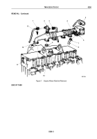
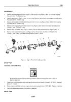
Remove rear water manifold section (Figure 2, Item 8) and o-ring (Figure 2, Item 10) from rear coupling
(Figure
2,
Item
11). Discard o-ring.
2.
Remove rear coupling (Figure 2, Item 11) and o-ring (Figure 2, Item 12) from center water manifold section
(Figure 2, Item 1). Discard o-ring.
3.
Remove center water manifold section (Figure 2, Item 1) and o-ring (Figure 2, Item 2) from front coupling
(Figure 2, Item 3). Discard o-ring.
4.
Remove front coupling (Figure 2, Item 3) and o-ring (Figure 2, Item 4) from front water manifold section
(Figure
2,
Item
5). Discard o-ring.
5.
Remove ether start safety valve (Figure 2, Item 9) from rear water manifold section (Figure 2, Item 8).
6.
Remove water temperature sending unit (Figure 2, Item 7) and water manifold shutoff drain valve
(Figure
2,
Item
6) from front water manifold section (Figure 2, Item 5).
M9492DAA
8
10
11
12
1
2
3
4
5
6
7
9
Figure 2.
Engine Water Manifold Disassembly.
END OF TASK
CLEANING AND INSPECTION
WARNING
Eyeshields must be worn during cleaning procedure. Failure to comply may result in injury or
death to personnel.
1.
Clean water manifold sections and couplings with wire brush and inspect (Volume 5, WP
0820). Replace if
broken or
cracked.
2.
Check heater shutoff drain valve for proper opening and closing (Volume 5, WP
0820). Replace if defective.
3.
Test water temperature sending unit. Replace if defective.
END OF TASK
TM 9-2320-272-23-2
0290
0290-4
Back to Top


