TM-9-2320-272-23-2 - Page 513 of 1417
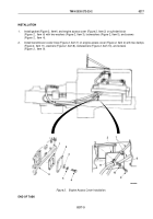
INSTALLATION
NOTE
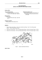
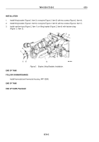
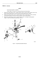
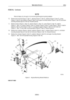
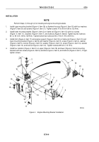
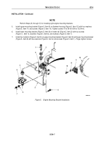
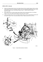
Perform Steps (1) through (4) for installing left engine mounting brackets.
1.
Install upper mounting bracket (Figure 4, Item 18) on flywheel housing (Figure 4, Item 19) with four washers
(Figure 4, Item 20) and screws (Figure 4, Item 21). Tighten screws 70 to 90 lb-ft (95 to 122 N·m).
2.
Install lower mounting bracket (Figure 4, Item 6) on frame rail (Figure 4, Item 10) with four screws
(Figure
4,
Item
11), washers (Figure 4, Item 7), and locknuts (Figure 4, Item 8). Tighten top two locknuts
80
to
95
lb-ft (109 to 129 N·m). Tighten bottom two locknuts 55 to 70 lb-ft (75 to 95 N·m).
3.
Install shim (Figure 4, Item 17) and engine support (Figure 4, Item 18) on frame rail (Figure 4, Item 10) and
lower mounting bracket (Figure 4, Item 6) with washer (Figure 4, Item 5), screw (Figure 4, Item 4), washer
(Figure 4, Item 5), locknut (Figure 4, Item 15), washer (Figure 4, Item 13), screw (Figure 4, Item 14), washer
(Figure 4, Item 13), and locknut (Figure 4, Item 12). Tighten locknuts 85 lb-ft (115
N·m).
4.
Install four isolators (Figure 4, Item 3) on upper (Figure 4, Item 18) and lower (Figure 4, Item 6) mounting
brackets with two screws (Figure 4, Item 9), washers (Figure 4, Item 2), and locknuts (Figure 4, Item 1). Finger-
tighten screws.
M9536DAA
19
18
20
21
1
2
3
3
4
5
6
7
8
9
10
11
12
13
14
15
5
16
17
18
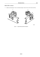
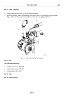
Figure 4.
Engine Mounting Bracket Installation.
TM 9-2320-272-23-2
0216
0216-6
Back to Top

