TM-9-2320-272-23-2 - Page 515 of 1417
INSTALLATION - Continued
8.
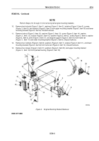
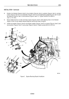
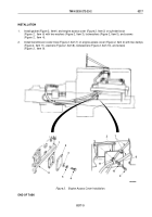
Position front bracket (Figure 6, Item 9), four isolators (Figure 6, Item 4), washers (Figure 6, Item 3), and two
screws (Figure 6, Item 2) on crossmember (Figure 6, Item 13) and install backing plate (Figure 6, Item 12) with
two washers (Figure 6, Item 10) and locknuts (Figure 6, Item 11). Tighten locknuts 75 to 85 lb-ft
(102
to
115
N·m).
9.
Slowly release tension on chain and lower engine (Figure 6, Item 5) while aligning holes in front bracket
(Figure
6, Item
9) and radiator bracket (Figure 6, Item 6) with holes in engine.
10.
Install front bracket (Figure 6, Item 9) and radiator bracket (Figure 6, Item 6) on engine (Figure 6, Item 5) with
four washers (Figure 6, Item 7) and screws (Figure 6, Item 8). Tighten screws 80 lb-ft (109
N·m).
1
M9003DAA
1
11
10
12
13
2
2
3
4
6
5
7
8
3
4
9
8
7
Figure 6.
Engine Mounting Bracket Installation.
TM 9-2320-272-23-2
0216
0216-8
Back to Top

