TM-9-2320-272-23-3 - Page 932 of 1469
INSTALLATION
1.
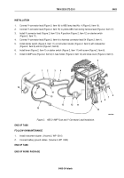
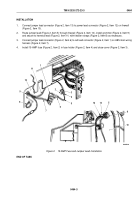
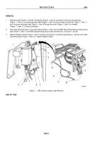
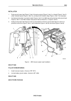
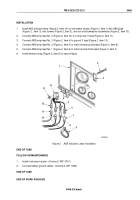
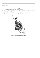
Route ground jumper lead (Figure 2, Item 4) through grommet (Figure 2, Item 2) on firewall (Figure 2, Item 3),
under instrument panel (Figure 2, Item 12), and secure with tiedown straps (Figure 2, Item 7) as necessary.
2.
Connect ground jumper Y-connector leads (Figure 2, Item 10) to ABS main wiring harness white ground lead
(Figure 2, Item 11) and ABS indicator lamp ground lead connector No. 3 (Figure 2, Item 9).
3.
Install ground jumper lead (Figure 2, Item 4) and protective control box ground lead (Figure 2, Item 5) on
protective control box (Figure 2, Item 1) with lockwasher (Figure 2, Item 6) and screw (Figure 2, Item 8).
9
10
4
11
12
4
3
2
5
6
7
8
1
M9411DAA
Figure 2.
ABS Ground Jumper Lead Installation.
END OF TASK
FOLLOW-ON MAINTENANCE
1.
Install instrument cluster. (Volume 2, WP
0310)
2.
Connect battery ground cables. (Volume 2, WP
0350)
END OF TASK
END OF WORK PACKAGE
TM 9-2320-272-23-3
0465
0465-3/4 blank
Back to Top

