TM-9-2320-272-23-4 - Page 1009 of 1393
INSTALLATION - Continued
NOTE
Direct assistant to maintain tension on hoist cable and observe that cable is winding properly.
5.
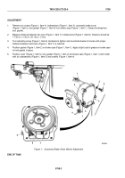
Wind cable (Figure 4, Item 2) on hoist winch drum (Figure 4, Item 1) until clevis (Figure 4, Item 3) end of cable
(Figure 4, Item 2) leaves ground.
6.
Thread cable clevis (Figure 4, Item 3) through snatch block (Figure 4, Item 15), over forward boom sheave
(Figure 4, Item 4), and back to snatch block.
7.
Remove nut (Figure 4, Item 14) and anchor bolt (Figure 4, Item 13) from snatch block (Figure 4, Item 15) and
install cable clevis (Figure 4, Item 3) with anchor bolt and nut.
8.
Install two spacers (Figure 4, Item 16) on forward boom (Figure 4, Item 12) with two screws
(Figure 4, Item 11) and locknuts (Figure 4, Item 8).
9.
Install rear cable guard (Figure 4, Item 7) over rear sheaves (Figure 4, Item 6) on boom (Figure 4, Item 5) with
four washers (Figure 4, Item 8), lockwashers (Figure 4, Item 9), and screws (Figure 4, Item 10).
10.
Raise snatch block (Figure 4, Item 15) and place in stowage position (TM 9-2320-272-10).
11.
Place hoist control in NEUTRAL position and stop vehicle (TM 9-2320-272-10).
TM 9-2320-272-23-4
0709
0709-6
Back to Top


