TM-9-2320-272-23-4 - Page 1001 of 1393
ADJUSTMENT
1.
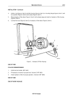
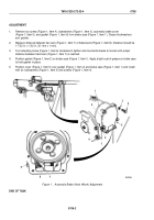
Remove six screws (Figure 1, Item 4), lockwashers (Figure 1, Item 3), automatic brake cover
(Figure 1, Item 5), and gasket (Figure 1, Item 6) from brake case (Figure 1, Item 1). Discard lockwashers
and
gasket.
2.
Measure distance between two ears (Figure 1, Item 7) of brake band (Figure 1, Item 8). Distance should be
1-7/32 in. ± 1/32 in. (31 mm ± 1 mm).
3.
Turn adjusting screw (Figure 1, Item 6) clockwise to tighten and counterclockwise to loosen until proper
distance between band ears (Figure 1, Item 7) is reached.
4.
Position gasket (Figure 1, Item 2) on brake case (Figure 1, Item 1). Apply a light coat of grease on brake case
to hold gasket in place.
5.
Position cover (Figure 1, Item 5) over gasket (Figure 1, Item 2) and brake case (Figure 1, Item 1) and install
with six lockwashers (Figure 1, Item 3) and screws (Figure 1, Item 4).
3
4
5
M9820DAA
1
2
6
7
8
6
Figure 1.
Automatic Brake (Hoist Winch) Adjustment.
END OF TASK
TM 9-2320-272-23-4
0708
0708-2
Back to Top


