TM-9-2320-272-23-4 - Page 735 of 1393
SIDE ROLLER DISASSEMBLY
NOTE
Repair procedures for both side rollers are the same. This procedure covers the left
side
roller.
1.
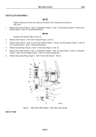
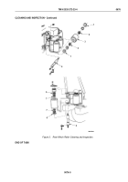
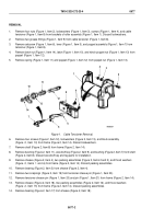
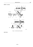
Remove two screws (Figure 1, Item 6), lockwashers (Figure 1, Item 7), and lockplate (Figure 1, Item 8) from
bracket (Figure 1, Item 3). Discard lockwashers.
NOTE
Assistant will help with Steps (2) and (3).
2.
Remove shaft (Figure 1, Item 5) from bracket (Figure 1, Item 3).
3.
Remove roller (Figure 1, Item 12), two thrust washers (Figure 1, Item 9), and felt washers (Figure 1, Item 10)
from bracket (Figure 1, Item 3). Discard felt washers.
4.
Remove two bearings (Figure 1, Item 11) from roller (Figure 1, Item 12).
5.
Remove two screws (Figure 1, Item 1), lockwashers (Figure 1, Item 14), plate (Figure 1, Item 2), and spacer
(Figure 1, Item 13) from bracket (Figure 1, Item 3). Discard lockwashers.
6.
Remove two grease fittings (Figure 1, Item 4) from shaft (Figure 1, Item 5).
3
4
5
M3033DAA
1
2
4
6
7
8
9
10
11
12
11
10
9
13
14
Figure 1.
Rear Winch Roller Repair - Side Roller Disassembly.
END OF TASK
TM 9-2320-272-23-4
0676
0676-2
Back to Top

