TM-9-2320-272-23-4 - Page 928 of 1393
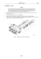
ASSEMBLY - Continued
NOTE
•
Install all parts in Steps (11) through (13) in their marked location and angle on
control
valve.
•
The three remaining spool valves are assembled into the control valve in the same way.
11.
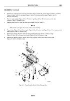
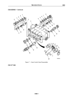
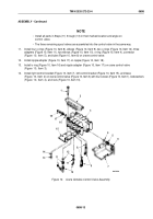
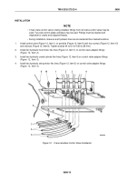
Install four o-rings (Figure 10, Item 8), elbows (Figure 10, Item 9), two o-rings (Figure 10, Item 12), three
adapters (Figure 10, Item 11), two elbows (Figure 10, Item 10), o-ring (Figure 10, Item 4), connector
(Figure
10,
Item
5), and tube (Figure 10, Item 6) on crane control valve.
12.
Install nipple adapter (Figure 10, Item 17) on nipple (Figure 10, Item 18).
13.
Install o-ring (Figure 10, Item 16) and nipple adapter (Figure 10, Item 17) on crane control valve
(Figure
10,
Item
3).
14.
Install right control bracket (Figure 10, Item 7), left control bracket (Figure 10, Item 15), and base
(Figure
10,
Item
2) on crane control valve (Figure 10, Item 3) with four screws (Figure 10, Item 1), lockwashers
(Figure
10,
Item
4), and nuts (Figure 10, Item 13).
M9676DAA
6
7
5
4
3
2
1
8
9
12
11
11
10
13
14
15
16
17
18
Figure 10.
Crane Gondola Control Valve Assembly.
TM 9-2320-272-23-4
0698
0698-13
Back to Top

