TM-9-2320-272-23-4 - Page 930 of 1393
INSTALLATION
NOTE
•
If new crane control valve is being installed, fittings from old crane control valve may be
used. Two side control plates and base may be used. Fittings must be cleaned and
inspected for cracks and stripped threads.
•
During installation, make sure all hydraulic lines are connected at their marked locations.
1.
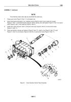
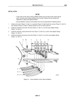
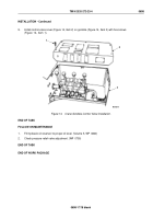
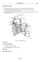
Install control valve (Figure 12, Item 1) on gondola (Figure 12, Item 9) with four screws (Figure 12, Item 10)
and locknuts (Figure 12, Item 8). Tighten screws 44 to 61 lb-ft (60 to 83 N·m).
2.
Install two hydraulic hoist motor flex lines (Figure 12, Item 7) on control valve adapter fittings
(Figure
12,
Item
2).
3.
Install two hydraulic crowd cylinder flex lines (Figure 12, Item 6) on control valve adapter fittings
(Figure
12,
Item
3).
4.
Install two hydraulic swing motor flex lines (Figure 12, Item 5) on control valve adapter fittings
(Figure
12,
Item
4).
M9928DAA
1
2
3
4
10
9
8
7
6
5
Figure 12.
Crane Gondola Control Valve Installation.
TM 9-2320-272-23-4
0698
0698-15
Back to Top

