TM-9-2320-272-23-4 - Page 943 of 1393
INSTALLATION
1.
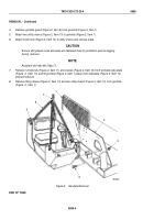
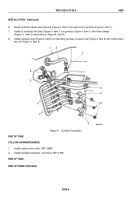
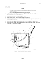
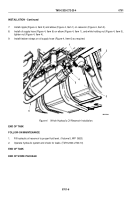
Install woodruff key (Figure 2, Item 13) in slot of gear shaft (Figure 2, Item 14) on hoist motor
(Figure
2,
Item
10).
2.
Install hoist motor (Figure 2, Item 10) on winch gearbox adapter (Figure 2, Item 8) with gasket
(Figure
2,
Item
11), four lockwashers (Figure 2, Item 6) and screws (Figure 2, Item 7). Tighten screws 60 to
70 lb-ft (81 to 95 N·m).
3.
Install two steel hydraulic lines (Figure 2, Item 4) on boom (Figure 2, Item 12) with four clamps
(Figure
2,
Item
1), washers (Figure 2, Item 2), and locknuts (Figure 2, Item 3).
4.
Connect two steel hydraulic lines (Figure 2, Item 4) to elbows (Figure 2, Item 9).
5.
Connect two hydraulic flex hoses (Figure 2, Item 5) to steel hydraulic lines (Figure 2, Item 4).
13
12
M6053DAA
1
2
3
6
10
7
8
9
10
11
4
5
14
4
Figure 2.
Hydraulic Hoist Winch Motor and Lines Installation.
END OF TASK
TM 9-2320-272-23-4
0700
0700-4
Back to Top


