TM-9-2320-272-24-3 - Page 44 of 799
TM 9-2320-272-24-3
4-49. OIL PUMP MAINTENANCE
THIS TASK COVERS:
a. Gear Backlash Test
b. Removal
c. Cleaning and Inspection
d. Installation
INITIAL SETUP:
APPLICABLE MODELS
REFERENCES (TM)
M939A2
TM 9-2320-272-10
TOOLS
TM 9-2320-272-24P
General mechanic’s tool kit (Appendix E, Item 1)
EQUIPMENT CONDITION
Dial indicator (Appendix E, Item 36)
Front gearcase cover removed (para. 4-48).
Torque Wrench (Appendix E, Item 144)
MATERIALS/PARTS
Oil pump kit (Appendix D, Item 494)
Pressure regulator plunger (Appendix D,
Item 524)
Washer (Appendix D, Item 716)
Engine oil (Appendix C, Item 50)
a. Gear Backlash Test
1.
2.
3.
4.
5.
6.
7.
8.
9.
10.
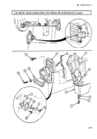
Install dial indicator on gear housing flange (1). Ensure anvil is positioned against tooth of drive
gear (4).
Holding idler gear (3) stationary, turn drive gear (4) against teeth of idler gear (3).
Set dial indicator to zero.
Turn drive gear (4) in opposite direction and take backlash reading.
Backlash reading must be between 0.003-0.013 in. (0.08-0.330 mm). If backlash reading is not
within limits, replace oil pump (6).
Position anvil of dial indicator on tooth of idler gear (3).
Holding crankshaft gear (2) stationary, turn idler gear (3) against teeth of crankshaft gear (2).
Set dial indicator to zero.
Turn idler gear (3) in opposite direction and take backlash reading.
Backlash reading must be between 0.003-0.013 in. (0.08-0.330 mm). If backlash reading is not
within limits, replace oil pump (6).
b. Removal
Remove four screws (5) and oil pump (6) from engine block (7).
4-308
Back to Top

