TM-9-2320-273-34 - Page 125 of 801
TM 9-2320-273-34
Section II. FAN CLUTCH ASSEMBLY
4-3. Description.
The fan clutch assembly has been specifically designed to improve the performance of
the engine. The fan clutch assembly is built to give greater horsepower transfer while reducing fuel con-
sumption, engine noise and overall weight. Air pressure from the actuator engages the fan when coolant
temperature rises above 190° F (88° C). When the coolant temperature decreases, the actuator dis-
engages the fan clutch which will prevent the fan from drawing horsepower from the engine.
4-4. Removal.
Remove the upper fan shroud, fan and fan clutch assembly from the vehicle. (Refer to
TM 9-2320-273-20).
4-5. Disassembly.
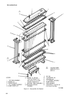
Clamp the fan clutch in a vise by bracket (10, fig. 4-2). Make sure the housing (16) is
facing in an upward position and proceed as follows:
a.
Remove plug assembly (19).
b.
Remove locknut (18) and spacer (17).
c.
The housing (16) and pulley (4) can now be slipped off of the shaft of the bracket assembly (9).
d.
Remove spacer (7) from the shaft of the bracket assembly (9).
e.
Separate the housing (16) from the pulley (4) by hand.
f.
Remove two of the eight screws (10).
g.
Install two No. 10-32 X 2“ screws three turns into holes vacated by the two screws just re-
moved. Remove the remaining six screws (10).
h.
facing (1)
.
board.
j.
k.
/.
press.
Remove the two No. 10-32 X 2“ screws and remove the thrust cap (3), spring (2), clutch
and spacer (14).
Remove piston (12) by tapping the housing (16) with piston facing down on a wood bench or
Remove the two O-rings (11) and (13) from the piston (12).
Remove two bearings (5) and spacer (15) from housing (16) with a suitable press.
Remove two bearings (5), spacer (7) and retaining ring (6) from pulley (4) with a suitable
4-6. Inspection.
Replace all worn or defective parts such as O-rings (11) and (13), clutch facing (1) and
four bearings (5). If it is found that the bearings (5) are in suitable condition for reuse, they should be
repacked with Dubois-MPG-2 or equal.
4-3
Back to Top


