TM-9-2320-328-13-P-1 - Page 560 of 1318
TM 9-2320-328-13&P-1
0065-4
DRAFT
0065
HWT0869
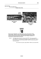
WARNING
ICON 3
Remove rings, wristwatches, neck chains, and any other jewelry before working
around vehicle.
Jewelry can catch on equipment and cause serious injury.
Jewelry
and tools may short across electrical circuits and cause damage to equipment, or
severe burns or electrical shock to personnel.
Step 4.
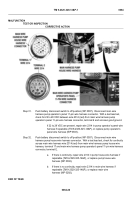
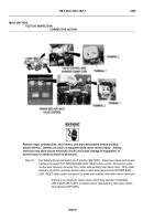
Pull battery disconnect switch to off position (WP 0007).
Open pump operator’s
panel (WP 0207).
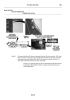
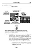
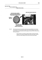
Disconnect valve control wire harness connector from DRIVER SIDE
AUX. INLET valve control.
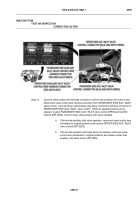
Disconnect valve control wire harness connector from
PASSENGER SIDE AUX. INLET valve control.
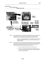
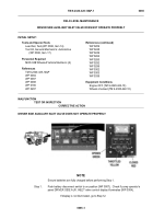
Connect driver side auxiliary inlet valve
control wire harness connector to PASSENGER SIDE AUX. INLET valve control.
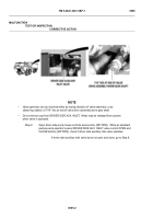
Push
battery disconnect switch to on position (WP 0007).
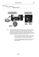
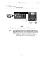
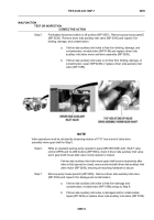
While an assistant monitors
operation of driver side auxiliary inlet valve, push pump operator’s panel PASSENGER
SIDE AUX. INLET valve control OPEN and CLOSE buttons (WP 0004).
Check if
PASSENGER SIDE AUX. INLET valve control OPENED (green) and CLOSED (red)
indicators illuminate before driver side auxiliary inlet valve is fully opened or closed.
If PASSENGER SIDE AUX. INLET valve control indicators do not illuminate
before driver side auxiliary inlet valve is fully opened or closed, reconnect
valve control wire harnesses to original positions and replace DRIVER SIDE
AUX. INLET valve control (WP 0209).
MALFUNCTION
TEST OR INSPECTION
CORRECTIVE ACTION
Back to Top

