TM-9-2320-328-13-P-1 - Page 561 of 1318
TM 9-2320-328-13&P-1
0065-5
DRAFT
0065
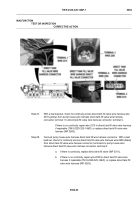
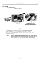
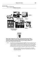
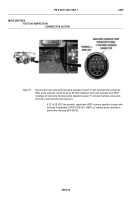
Step 5.
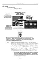
Pull battery disconnect switch to off position (WP 0007).
Remove pump house panel E
(WP 0339).
Remove driver side auxiliary inlet valve (WP 0186) and inspect it for
binding, damage, and contamination.
a.
If driver side auxiliary inlet valve is free from binding, damage, and
contamination, reinstall valve (WP 0186) and replace driver side
auxiliary inlet valve motor and drive assembly (WP 0248).
b.
If driver side auxiliary inlet valve is not free from binding, damage, or
contamination, repair (WP 0249) or replace driver side auxiliary inlet
valve (WP 0186).
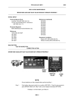
HWT0557
NOTE
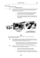
Valve operations must be checked by observing rotation of 7/16” hex at end of valve drive
assembly worm gear shaft for Step 6.
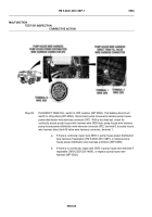
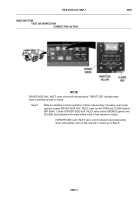
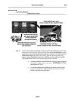
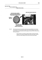
Step 6.
While an assistant pushes pump operator’s panel DRIVER SIDE AUX. INLET valve
control OPEN and CLOSE buttons (WP 0004), check if driver side auxiliary inlet valve
worm gear shaft moves after valve is fully opened or closed.
If driver side auxiliary inlet valve worm gear shaft moves excessively after
valve is fully opened or closed, remove and reinstall driver side auxiliary inlet
valve motor (WP 0248), ensuring all mounting hardware is secure.
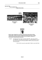
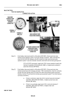
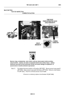
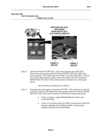
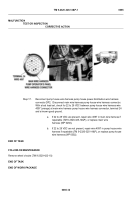
Step 7.
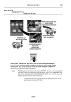
Remove pump house panel E (WP 0339).
Remove driver side auxiliary inlet valve
(WP 0186) and inspect it for damage and contamination.
a.
If driver side auxiliary inlet valve is free from damage and
contamination, reinstall valve (WP 0186) and go to Step 8.
b.
If driver side auxiliary inlet valve is damaged and/or contaminated,
repair (WP 0249) or replace driver side auxiliary inlet valve (WP 0186).
MALFUNCTION
TEST OR INSPECTION
CORRECTIVE ACTION
Back to Top

