TM-9-2320-328-13-P-2 - Page 718 of 1390
TM 9-2320-328-13&P-2
0209-2
DRAFT
0209
-
-
-
-
-
-
-
-
-
-
-
-
-
-
-
-
-
-
-
-
-
-
-
-
-
-
-
-
-
-
-
-
-
-
-
-
-
-
3.
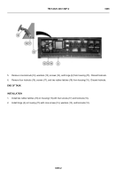
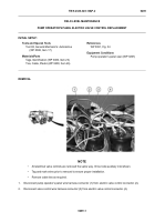
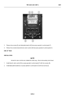
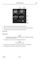
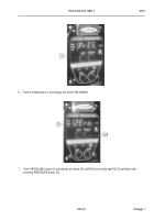
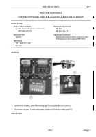
Remove two screws (5) and data plate bracket (6) from pump operator’s control panel (7).
4.
Remove four screws (8) and electric valve control (9) from pump operator’s control panel (7).
END OF TASK
INSTALLATION
NOTE
All electric valve controls are installed the same way.
Driver side auxiliary inlet shown.
1.
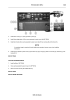
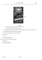
Install electric valve control (9) on pump operator’s control panel (7) with four screws (8).
2.
Install data plate bracket (6) on pump operator’s control panel (7) with two screws (5).
HWT1794
Back to Top

