TM-9-2320-328-13-P-2 - Page 721 of 1390
TM 9-2320-328-13&P-2
0210-1
DRAFT
0210
Change 1
FIELD LEVEL MAINTENANCE
PUMP OPERATOR'S PANEL ELECTRIC VALVE CONTROL METER REPLACEMENT AND CALIBRATION
INITIAL SETUP:
REMOVAL
-
-
-
-
-
-
-
-
-
-
-
-
-
-
-
-
-
-
-
-
-
-
-
-
-
-
-
-
-
-
-
-
-
-
-
-
-
NOTE
•
Tag and mark connectors prior to removal to ensure proper installation.
•
Remove cable ties as required.
•
Both electric valve control meters are removed the same way.
Passenger side discharge
electric valve control meter shown.
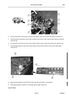
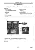
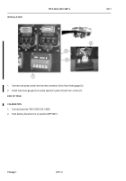
1.
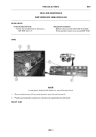
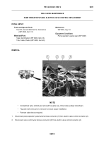
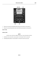
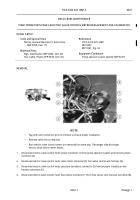
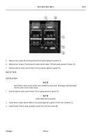
Disconnect electric valve control meter power connector (1) from pump operator’s panel wire harness power
connector (2).
2.
Disconnect electric valve control meter valve motor connector (3) from valve control wire harness (4).
3.
Disconnect electric valve control meter pressure transducer connector (5) from pressure transducer wire
harness connector (6).
4.
Disconnect electric valve control meter flow sensor connector (7) from flow sensor wire harness connector (8).
-
-
-
-
-
-
-
-
-
-
-
-
-
-
-
-
-
-
-
-
-
-
-
-
-
-
-
-
-
-
-
-
-
-
-
-
-
-
..
..
..
..
..
..
..
..
..
..
..
..
..
..
..
HWT1963A
Tools and Special Tools
Tool Kit, General Mechanic’s: Automotive
(WP 0398, Item 17)
Materials/Parts
Tags, Identification (WP 0400, Item 23)
Ties, Cable, Plastic (WP 0400, Item 26)
References
TM 9-2320-325-14&P
WP 0007
WP 0391, Fig. 34
Equipment Conditions
Pump operator’s panel opened (WP 0207)
Back to Top

