TM-9-2320-328-13-P-2 - Page 722 of 1390
TM 9-2320-328-13&P-2
0210-2
DRAFT
0210
Change 1
-
-
-
-
-
-
-
-
-
-
-
-
-
-
-
-
-
-
-
-
-
-
-
-
-
-
-
-
-
-
-
-
-
-
-
-
-
-
5.
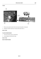
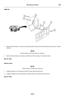
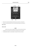
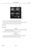
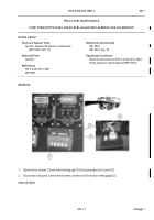
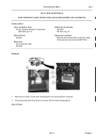
Remove two screws (9) and bracket (10) from pump operator’s panel (11).
6.
Remove four screws (12) and electric valve control meter (13) from pump operator’s panel (11).
7.
Remove electric valve control meter (13) from pump operator’s panel (11).
END OF TASK
INSTALLATION
NOTE
Both electric valve control meters are installed the same way.
Passenger side discharge
electric valve control meter shown.
1.
Position electric valve control meter (13) on pump operator’s panel (11).
NOTE
Install cable ties as required.
2.
Install electric valve control meter (13) on pump operator’s panel (11) with four screws (12).
3.
Install bracket (10) on pump operator’s panel (11) with two screws (9).
HWT2800
Back to Top

