TM-9-2330-202-13-P - Page 158 of 552
REMOVAL - Continued
2.
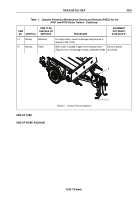
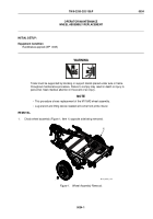
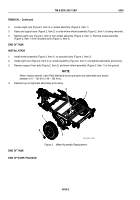
Loosen eight nuts (Figure 2, Item 4) on wheel assembly (Figure 2, Item 1).
3.
Raise and support axle (Figure 2, Item 2) on side where wheel assembly (Figure 2, Item 1) is being removed.
4.
Remove eight nuts (Figure 2, Item 4) from wheel assembly (Figure 2, Item 1). Remove wheel assembly
(Figure 2, Item 1) from shoulder bolts (Figure 2, Item 3).
END OF TASK
INSTALLATION
1.
Install wheel assembly (Figure 2, Item 1) on shoulder bolts (Figure 2, Item 3).
2.
Install eight nuts (Figure 2, Item 4) on wheel assembly (Figure 2, Item 1) and tighten alternately and evenly.
3.
Remove support from axle (Figure 2, Item 2) and lower wheel assembly (Figure 2, Item 1) to the ground.
NOTE
When mission permits, have Field Maintenance torque eight nuts alternately and evenly
between 110 – 120 Ib-ft (149 – 163 N•m).
4.
Recheck lug nut tightness alternately and evenly.
1
1
4
2
3
M116_M101_023A
Figure 2.
Wheel Assembly Replacement.
END OF TASK
END OF WORK PACKAGE
TM 9-2330-202-13&P
0034
0034-2
Back to Top

