TM-9-2330-202-13-P - Page 176 of 552
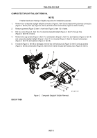
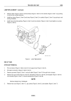
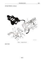
COMPOSITE STOPLIGHT-TAILLIGHT INSTALLATION
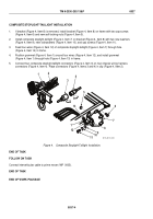
1.
If bracket (Figure 4, Item 8) is removed, install bracket (Figure 4, Item 8) on frame with two cap screws
(Figure 4, Item 6) and new self-locking nuts (Figure 4, Item 5).
2.
Install composite stoplight-taillight (Figure 4, Item 7) on bracket (Figure 4, Item 8) with two new washers
(Figure 4, Item 9), new lockwashers (Figure 4, Item 10), and cap screws (Figure 4, Item 11).
3.
Feed four wires (Figure 4, Item 12) of composite stoplight-taillight (Figure 4, Item 7) through hole
(Figure 4, Item 14) in frame.
4.
Position grommet (Figure 4, Item 1) around four wires (Figure 4, Item 12), and install grommet
(Figure 4, Item 1) through hole (Figure 4, Item 13) in frame.
5.
Connect four composite stoplight-taillight connectors (Figure 4, Item 3) on four chassis wiring harness
connectors (Figure 4, Item 4). Place connectors (Figure 4, Items 3 and 4) in clip (Figure 4, Item 2).
1
1
2
3
4
5
6
7
8
9
10
11
12
13
M116_M101_052
Figure 4.
Composite Stoplight-Taillight Installation.
END OF TASK
FOLLOW ON TASK
Connect intervehicular cable to prime mover (WP
0005).
END OF TASK
END OF WORK PACKAGE
TM 9-2330-202-13&P
0037
0037-4
Back to Top

