TM-9-2330-227-14-P - Page 153 of 576
2-22
TM 9-2330-227-14&P
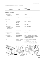
CONNECTOR RECEPTACLE, 24-VOLT - CONTINUED
ACTION
LOCATION
ITEM
REMARKS
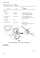
INSTALLATION
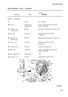
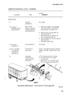
5.
Connector
Put in place.
receptacle (2)
6.
Connector
Eight harness
a.
receptacle (2) and
wires (7), connector
wire harness (6)
receptacle leads (8),
and connectors (9)
b.
c.
d.
c.
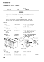
7.
Connector
Cover assembly (1)
receptacle (2)
8.
Cover assembly
Two screws (4)
(1), connector
and nuts (5)
receptacle (2),
and frame (3)
9.
Remaining
screws (4), two
ground wires (10),
and nuts (5)
Using wire strippers, strip insulation
from ends of wires (7) and leads (8),
equal to depth of connectors (9).
Slide one end of one connector (9)
onto one of wires (7).
Slide other ends of connectors (9)
onto corresponding leads (8).
Using crimping tool, crimp connectors
(9) at both ends.
Tape each connector (9).
Put in place.
Screw in, and tighten using two 7/16-inch
openend wrenches, leaving bottom holes
open.
a. Put remaining screw (4) in place.
b. Put ground wires (10) in place
over screw (4).
c. Screw on nut (5), and tighten using
two 7/16-inch open-end wrenches.
4-75
Back to Top

