TM-9-2330-227-14-P - Page 161 of 576
TM 9-2330-227-14&P
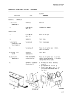
SERVICE BRAKES, ONE-WHEEL CYLINDER OPTION - CONTINUED
ACTION
LOCATION
ITEM
REMARKS
ADJUSTMENT - CONTINUED
3.
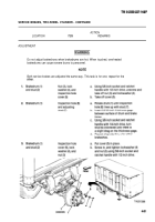
Continued
4.
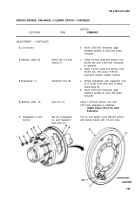
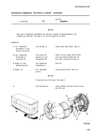
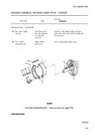
Backing plate (6)
5.
Brakedrum (1)
6.
Backing plate (6)
7.
b.
Anchor pin (10) and
a.
locknut (7)
b.
Inspection hole (8)
a.
b.
Cam nut (11)
Insert 0.005-inch thickness gage
between surface of drum and brake
lining (9).
Using 1/2-inch open-end wrench, turn
anchor pin until 0.005-inch clearance
is obtained.
Using 1/2-inch open-end wrench, hold
anchor pin, and using 11/8-inch
open-end wrench, tighten locknut.
Rotate brakedrum until inspection hole
is 11/2-inch from other end of same
brake lining (9).
Insert 0.010-inch thickness gage
between surface of drum and brake
lining (9).
Using 11/16-inch wrench, turn until
0.010-inch clearance is obtained.
Repeat steps 2 thru 6 for other
brakeshoe.
Brakedrum (1) and
Nut (3), Iockwasher
Put on, and tighten using 5/8-inch socket
bolt (2)
(4), and inspection
and ratchet handle with 1/2-inch drive.
hole cover (5)
4-83
Back to Top

