TM-9-2330-227-14-P - Page 160 of 576
TM 9-2330-227-14&P
SERVICE BRAKES, TWO-WHEEL CYLINDER - CONTINUED
ADJUSTMENT -
TASK ENDS HERE
SERVICE BRAKES,
CONTINUED
FOLLOW-ON
NOT E
MAINTENANCE:
1.
Install tire and wheel assembly (page 4-148.1).
2. Test operation of brakes (page 2-23).
ONE-WHEEL CYLINDER OPTION
This task covers:
Adjustment (page 4-82)
INITIAL SETUP
Tools
Personnel Required
Gage, thickness, 0.005-inch
Gage, thickness, 0.010-inch
Handle, ratchet, 1/2-inch drive
Socket, 1/2-inch drive, 5/8-inch
Wrench, open-end, 1/2-inch
Wrench, open-end, 11/16-inch
Wrench, open-end, 11/16-inch
Wrench, open-end, 11/8-inch
One
Equipment Condition
Tire and wheel assembly removed (page 4-148.1).
ACTION
LOCATION
ITEM
REMARKS
ADJUSTMENT
NOT E
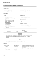
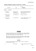
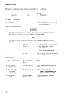
Both service brakes are adjusted the same way. This task is for one; repeat for others.
1.
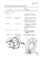
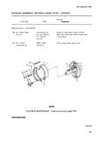
Brakedrum (1) and
bolt (2)
2.
Backing plate (6)
3.
Brakedrum (1)
4-82
Change 1
Nut (3), lockwasher
Using 5/8-inch socket and ratchet
(4), and inspection
handle with 1/2-inch drive, unscrew
hole cover (5)
and take off.
Locknut (7)
Using 11/16-inch open-end wrench,
loosen.
Inspection hole (8)
a. Rotate brakedrum (1) until inspection
hole (8) is 11/2-inches from end of
one brake lining (9) nearest
anchor pin (10).
Back to Top

