TM-9-2330-227-14-P - Page 304 of 576
page 5-30
TM 9-2330-227-14&P
WALL RECEPTACLE CABLES - CONTINUED
ACTION
LOCATION
ITEM
REMARKS
INSTALLATION - CONTINUED
NOT E
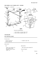
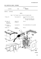
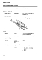
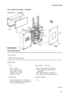
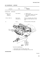
Steps 37 thru 40 connect left side cables to circuit breaker box, and steps 41 thru 44
connect right side cables to circuit breaker box.
37.
Terminal (1)
Cable (2)
Terminal block (4)
Cable (5)
Terminal (7)
Cable (8)
Terminal block (4)
Cable (10)
Circuit breaker
box (12)
Cover (13)
Base (15)
Cable (2) with metal
band 38D
Screw (3)
Cable (5) with
metal band 38S
Screw (6)
Cable (8) with metal
band 38C
Screw (9)
Cable (10) with
metal band 38R
Screw (11)
Cover (13)
Four screws (14)
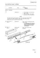
Cover sections (16)
Place in position.
Tighten using 3/16-inch flat-tip
screwdriver.
Place in position.
Tighten using 3/16-inch flat-tip
screwdriver.
Place in position.
Tighten using 3/16-inch flat-tip
screwdriver.
Place in position.
Tighten using 3/16-inch flat-tip
screwdriver.
Place in position.
Screw in, and tighten using 3/16-inch
flat-tip screwdriver.
Using ball-peen hammer, tap in the full
length of wall receptacle base.
Back to Top

