TM-9-2330-227-14-P - Page 302 of 576
TM 9-2330-227-14&P
WALL RECEPTACLE CABLES - CONTINUED
ACTION
LOCATION
ITEM
REMARKS
INSTALLATION
25.
26.
27.
28.
29.
30.
31.
32.
5-28
NOT E
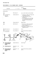
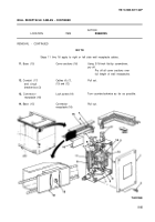
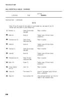
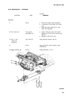
Steps 25 thru 36 apply to right or left side wall receptacle cables.
New cables
a. From bulk cable, cut new cables
(1) and (2)
to same length as old cables.
b. Strip insulation back 3/4-inch (19 mm)
from each end using wire strippers.
NOT E
If end of cable is connected to shiny silver contact screw to start with, that cable should
be connected to silvery screw at each receptacle. The same applies to the cable
connected to bronze finish contact screw.
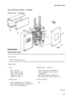
Contact screw (3)
at receptacle (4)
Cable (1)
Contact screw (5)
at receptacle (6)
Cable (1)
Contact screw (7)
at receptacle (4)
Cable (2)
Contact screw (8)
at receptacle (6)
Cable (1)
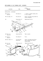
Wrap bare wire around screw.
Screw (3)
Tighten using 3/16-inch flat-tip
screwdriver.
Cable (1)
a.
b.
Strip 3/4-inch (19 mm) insulation
from cable (1) at a point 2-ft
(50.8 mm) from contact screw (3).
Wrap bare wire around screw.
Screw (5)
Tighten using 3/16-inch flat-tip
screwdriver.
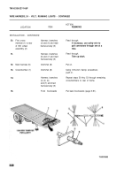
Repeat steps 26 thru 29 until cable
is connected to all receptacles.
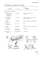
Cable (2)
Wrap bare wire around screw.
Screw (7)
Tighten using 3/16-inch flat-tip
screwdriver.
Cable (2)
a. Strip 3/4-inch (19 mm) insulation
from cable (2) at a point 2-ft
(50.8 mm) from contact screw (7).
b. Wrap bare wire around screw.
Back to Top

