TM-9-2330-335-14-P - Page 254 of 640
TM 9-2330-335-14&P
0050-4
0050
INSTALLATION
00050
1.
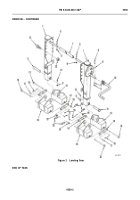
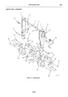
Install two lanyards (Figure 3, Item 16) into landing leg (Figure 3, Item 1) using two new pop rivets (Figure 3,
Item 17).
2.
Install front shoe assembly (Figure 3, Item 13) on rear shoe assembly (Figure 3, Item 18) using two hitch pins (Figure 3,
Item 20), washers (Figure 3, Item 19), ties (Figure 3, Item 14), and pins (Figure 3, Item 15).
3.
Install shoe assembly on landing leg (Figure 3, Item 1) using pin (Figure 3, Item 11), hex screw (Figure 3, Item 12), and
new self-locking nut (Figure 3, Item 9).
4.
Install landing leg (Figure 3, Item 1) onto landing leg upper bracket using eight bolts (Figure 3, Item 21) and new locknuts
(Figure 3, Item 22).
5.
Install landing leg (Figure 3, Item 1) onto landing leg lower bracket using three bolts (Figure 3, Item 21) and new locknuts
(Figure 3, Item 22).
6.
Repeat steps 1 thru 5 for remaining landing leg.
7.
Install landing leg (Figure 3, Item 1) onto cross drive shaft (Figure 3, Item 7) using two bolts (Figure 3, Item 6) and new
self-locking nuts (Figure 3, Item 9).
8.
Install landing leg crank (Figure 3, Item 10) onto landing leg (Figure 3, Item 1) using bolt (Figure 3, Item 6), two washers
(Figure 3, Item 8), and new self- locking nut (Figure 3, Item 9).
Back to Top

