TM-9-2330-342-23-P - Page 110 of 1348
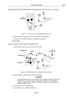
TEST EQUIPMENT SETUP FOR CONTINUITY AND RESISTANCE TESTS 91 AND 92 - Continued.
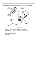
J5 CONNECTOR
ICE BOX
DC OUTPUT
CABLE
W1 CABLE
J1 CONNECTOR
RED
LEAD
POWER
SWITCH
DCA
CONNECTOR
W1 CABLE
BLACK
LEAD
AC INPUT
DC INPUT
FUSE
POWER
CONVERTER
110 VAC
SUPPLY CABLE
Figure 26.
MSD/ICE Power Setup.
7. Connect 110 vac supply cable or NATO slave cable to power converter.
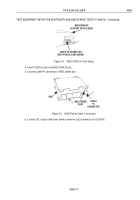
8. Connect W1 cable to J1 connector on ICE BOX and to vehicle DCA connector.
9. Place ICE BOX power switch in NATO or DCA setting.
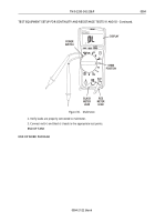
10. If performing offset procedure, short red (+) and black (-) leads together.
11. Connect red (+) and black (-) leads to the appropriate test points.
END OF TASK
Maintenance Support Device (MSD) Serial ICE Kit Setup
1. Connect button probe cable to J4 connector on ICE BOX.
TM 9-2330-342-23&P
0004
0004-18
Back to Top


