TM-9-2330-342-23-P - Page 101 of 1348
TEST EQUIPMENT SETUP FOR VOLTAGE TEST 89 - Continued
Soldiers Portable On-system Repair Tool (SPORT) Setup
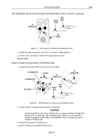
1. Connect button probe cable to J4 connector on ICE BOX.
W2 CABLE
J5 CONNECTOR
J4 CONNECTOR
P3
CONNECTOR
P2
CONNECTOR
ICE BOX
RED
LEAD
BLACK
LEAD
Figure 12.
SPORT Setup for Voltage Test.
2. Connect cable P1 connector to J6 connector on ICE BOX.
CAUTION
If removing PCMCIA card, ensure PCMCIA drive is properly shutdown through Eject
Hardware icon on lower right side of desktop screen toolbar or by shutting down
Soldiers Portable On-system Repair Tool (SPORT). Failure to comply may result in
damage to PCMCIA card.
3. Connect P2 connector to PCMCIA card.
4. Insert PCMCIA card into SPORT PCMCIA slot.
5. Connect P3 end of cable to SPORT power port.
6. Attach cable grounding wire to SPORT ground stud.
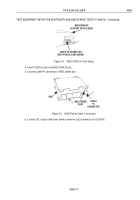
7. Connect power cable to J5 ICE BOX connector and to vehicle NATO connector.
8. Connect W1 cable to J1 connector on ICE BOX and to vehicle DCA connector (if available).
9. Place ICE BOX power switch in NATO or DCA setting.
10. Connect red (+) and black (-) leads to the appropriate test points.
END OF TASK
Maintenance Support Device (MSD) Standard (PCMCIA) ICE Kit Setup
1. Connect button probe cable to J4 connector on ICE BOX.
2. Connect cable P1 connector to J6 connector on ICE BOX.
TM 9-2330-342-23&P
0004
0004-9
Back to Top


