TM-9-2330-342-23-P - Page 106 of 1348
TEST EQUIPMENT SETUP FOR VOLTAGE TEST 89 - Continued
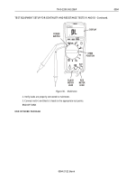
DISPLAY
DC VOLTAGE
POSITION
POWER
SWITCH
BLACK METER
LEAD
RED METER
LEAD
Figure 20.
Multimeter.
2. Verify leads are properly connected to multimeter.
3. Connect red (+) and black (-) leads to the appropriate test points.
END OF TASK
TEST EQUIPMENT SETUP FOR CONTINUITY AND RESISTANCE TESTS 91 AND 92.
•
Contact Test Set (CTS)
•
Soldiers Portable On-system Repair Tool (SPORT)
•
Maintenance Support Device (MSD) Standard (PCMCIA) ICE Kit
•
Maintenance Support Device (MSD) Serial ICE Kit
•
Multimeter
Contact Test Set (CTS) Setup
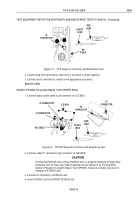
1. Connect button probe cable (W2) to J4 connector in back of CTS.
TM 9-2330-342-23&P
0004
0004-14
Back to Top


