TM-9-2330-342-23-P - Page 240 of 1348
CONDITION/INDICATION
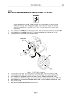
Are 22 to 28 vdc measured at vehicle 24 vdc (12 terminal) connector, terminal C?
DECISION
Voltage OK - Go to (Step 2 - Does at least one blackout taillight operate when power is applied?).
Voltage Faulty - Troubleshoot Trailer Electrical System Does Not Work. Refer to vehicle Field Maintenance
manual (WP
0190).
STEP 2
Does at least one blackout taillight operate when power is applied?
NOTE
•
The following procedures cover the left blackout taillight, but they apply to both
blackout taillights.
•
All electrical wires and components listed in this troubleshooting procedure are
illustrated and located in Electrical System Schematic.
1.
Have assistant turn engine start switch to ON. Refer to vehicle Operator's manual (WP
0190).
2.
Have assistant turn ON Blackout Marker selector switch. Refer to vehicle Operator's manual (WP
0190).
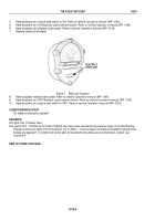
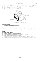
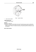
BLACKOUT
TAILLIGHT
Figure 1.
Blackout Taillight.
3.
Have assistant turn ON BLACKOUT MARKER switch. Refer to vehicle Operator's manual (WP
0190).
4.
Observe blackout taillights.
CONDITION/INDICATION
Does at least one blackout taillight operate when power is applied?
DECISION
One Light On - Go to (Step 3 - Are 22 to 28 vdc measured on wire 1680C/24 at LED composite light?).
All Lights Out - Go to (Step 5 - Are 22 to 28 vdc measured between terminal A and D on trailer end of 24 vdc
cable?).
TM 9-2330-342-23&P
0020
0020-2
Back to Top


