TM-9-2330-342-23-P - Page 508 of 1348
INSTALLATION - Continued
1
2
3
4
5
6
7
8
9
10
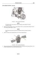
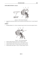
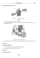
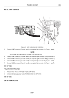
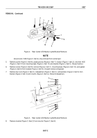
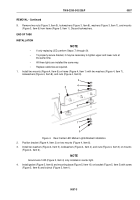
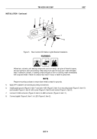
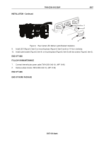
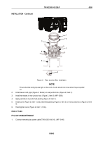
Figure 4.
LED Composite Light Installation.
3.
Connect 1008C connector (Figure 4, Item 1) on composite light connector 21 (Figure 4, Item 4).
NOTE
Perform Step (4) for left side only and Step (5) for right side only.
4.
Connect 1004C connector (Figure 4, Item 10) on composite light connector 22 (Figure 4, Item 5).
5.
Connect 1003C connector (Figure 4, Item 10) on composite light connector 22 (Figure 4, Item 5).
6.
Connect 1678C connector (Figure 4, Item 9) on composite light connector 23 (Figure 4, Item 6).
7.
Connect 1680C connector (Figure 4, Item 8) on composite light connector 24 (Figure 4, Item 7).
END OF TASK
FOLLOW-ON MAINTENANCE
1.
Remove wheel chocks (TM 9-2330-342-10). (WP
0190)
2.
Connect intervehicular power cable (TM 9-2320-342-10). (WP
0190)
END OF TASK
END OF WORK PACKAGE
TM 9-2330-342-23&P
0056
0056-4
Back to Top

