TM-9-2330-356-14
SEMITRAILER, TANK: 5000 GALLON, BULK HAUL, SELF LOAD/UNLOAD M967 AND M967A1; SEMITRAILER, TANK: 5000 GALLON, FUEL DISPENSING, AUTOMOTIVE M969 AND M969A1; SEMITRAILER, TANK: 5000 GALLON, FUEL DISPENSING, UNDER/OVERWING AIRCRAFT M970 AND M970A1
TECHNICAL MANUAL; OPERATOR’S, UNIT, DIRECT SUPPORT, AND GENERAL SUPPORT MAINTENANCE MANUAL
OCTOBER 1990
TM-9-2330-356-14 - Page 245 of 528
TM 9-2330-356-14
(3) Tighten inner adjustment nut to minimum of 75 ft-
lb to ensure proper seating of e bearings and cup in wheel hub.
(4) Loosen inner adjustment nut so wheel will turn
freely.
(5) Retighten inner adjustment nut to 50 ft-lb while
rotating wheel, in order to properly position bearings for final
adjustment.
(6) Looscn inner adjustment nut 1/3 turn.
WARNING
Failure to beck off the inner adjustment nut could
cause bring and axle spindle overheating or dam-
age,.which could result m the wheel Iocking up or
coming off during vehicle operation, resulting in
property damage or loss of life.
(7) Install spindle nut lockwasher so that dowel on inner
nut alines with hole in lockwasher and washer tang tits in spindle
keyway.
WARNING
Failure to torque outer locknut properly could
cause wheel to come off during vehicle operation,
which could result m property damage or loss of life.
If an external tan or setscrew-type lockwaaher
is used, it is important to remember to bend tabs over
outer locknut, or to install the setscrew in lockwasher,
after the outer nut has been properly torqued.
(8) Install outer locknut and tighten to 250-400 ft-lb.
(9) Apply a light coat of grease (Item 17, Appendix E)
to new hub cap gas et and position gasket on hub.
(10) Install hub cap and secure with six bolts and
lockwashers. Tighten bolts to 16-20 ft.-lb.
(11) Pressurize air system by attaching towing vehicle
air lines to semitrailer and starting towing vehicle engine.
(12)
(13)
(para 2-4).
(14)
Adjust brakes (para 4-34).
Manually release fail-safe chamber power spring
Remove any blocking from tires.
h.
Wheel Studs (M967, M969, and M970 except M970 SN
TC-0843, TC-0844, and TC-103 thru TC-178).
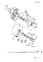
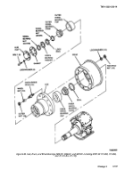
(1) Removal (Fig. 4-86).
(a) Remove tire and wheel.
(b) Remove five screws that fasten brake drum to
hub and remove brake drum.
(c Remove ten capscrews that fasten hub cap to
hub. Remove hub cap and gasket.
(d) Using wheel bearing nut wrench, remove outer
wheel bearing nut, lock ring, and inner wheel bearing nut.
(e) Remove outer wheel bearing cone.
(f) Remove hub from axle spindle being careful
not to damage wiper and seal.
(g) l)rive broken wheel studs from hub.
(2)
Installation (Fig. 4-86).
(a) Install wheel studs into hub. Use a hammer and
driver to install studs.
(b) If wiper remained with axle spindle when hub
was removed, remove roper and install in hub. Install outer wheel
bearing cone in hub.
(c) Pack bearings from large end of cone
with grease (item 17, Appendix E) making sure all cavities
between rollers and cup are filled.
(d) Install hub onto axle spindle. Install
inner wheel bearing nut, lock ring, and outer wheel
bearing nut, but do not tighten.
(e) Install brake drum over the hub and
secure with five screws.
(f) Install wheels and adjust wheel bearings.
i
Wheel Studs (M967A1, M969A1, and M970A1
including M970 SN TC-0843, TC-0844, and TC-103
thru TC-178).
(1)
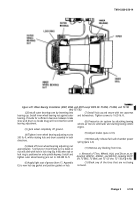
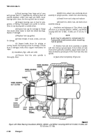
Removal (Fig. 4-88).
(a)
Remove wheels and tires.
(b)
Remove six bolts and lockwashers that
fasten the hub cap to the hub. Remove hubcap and gasket.
(c)
Using wheel bearing nut wrench remove
outer wheel bearing nut, wheel bearing washer, lock ring,
and inner wheel bearing nut.
(d)
Remove outer wheel bearing crone.
(e)
Remove hub and drum from axle spindle
being careful not to damage seal.
(f)
Remove nuts, lockwashers, and broken
studs from hub and drum.
(2) Installation (Fig. 4-88).
(a)
Install studs (short side from shoulder
facing out) into hub and drum and secure studs with
lockwashers and nuts.
(b)
Install hub and drum onto axle spindle.
(c) Pack bearing from large end of cone with
grease (item 17, Appendix E) making sure all cavities
between rollers and cup are filled.
(d)
Install outer wheel bearing cone in hub.
(e)
Install inner bearing nut, lock ring,
wheel bearing washer, and outer wheel bearing nut, but do
not tighten.
(f)
Install wheels and tires and adjust wheel
bearings.
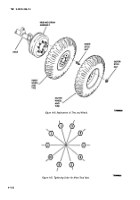
4-50. Tire and Tube
a
Service. Gage tires for correct pressure. For hard
surface roads, inflate to 60 psi; for cross-country and sand,
inflate to 40 psi.
Change 3
4-109
Back to Top

