TM-9-2330-356-14
SEMITRAILER, TANK: 5000 GALLON, BULK HAUL, SELF LOAD/UNLOAD M967 AND M967A1; SEMITRAILER, TANK: 5000 GALLON, FUEL DISPENSING, AUTOMOTIVE M969 AND M969A1; SEMITRAILER, TANK: 5000 GALLON, FUEL DISPENSING, UNDER/OVERWING AIRCRAFT M970 AND M970A1
TECHNICAL MANUAL; OPERATOR’S, UNIT, DIRECT SUPPORT, AND GENERAL SUPPORT MAINTENANCE MANUAL
OCTOBER 1990
TM-9-2330-356-14 - Page 237 of 528
TM 9-2330-356-14
(3) Disconnect tubing from fitting and remove
the insert, compression sleeve and nut on both ends of
tubing. Release the clips and pull tubing through
grommets.
NOTE
Tubing is stocked in bulk lengths. Measure
original tubing and cut new tubing to same
length.
(4) Install tubing on semitrailer and bend clips
down securely to hold tubing in position.
Section XIII.
4-49. Wheels, Hubs, and Drums
WARNING
Spare tire vveighs 190 pounds. Four-person
lift, or suitable lifting device, is required.
(5) Trim ends of tubing to get a smooth, square
cut. Slide tubing nut on end of tube. Slide impression
sleeve over end oft tubing. Install tubing insert. Connect
tubing to adapter fitting and tighten tubing nut securely.
Do the same procedure on both ends.
(6) Check replaced tubing for leaks. No leaks are
permitted.
(7) Remove blocking from semitrailer wheels.
d. Air Line Fittings.
Use antiseize tape (item 28,
Appendix E) on all male pipe threads. Take care not to let
any of the tape get into the system.
MAINTENANCE OF WHEELS, HUBS, AND DRUMS
a
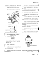
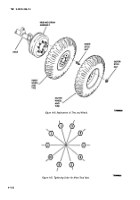
Tire and Wheel Replacement (Fig. 4-84).
(1)
Removal.
Bbck any of the tires that are not
being removed. Jack up axle until tire is clear of ground.
Support axle with jack stand or blocking. Remove outer
stud nuts (fig. 4-84). Remove tire and wheel assembly. If
inner tire must be removed, remove the ten inner stud
nuts (fig. 4-84), and remove inner tire and wheel assembly.
(2) Repair.
(a)
Repair tubes (para 4-50).
(b)
Refer to general support maintenance
for repair of tires.
(3)
Installation.
Position inner wheel over studs
on axle hub. Replace ten inner stud nuts (fig. 4-84), lower
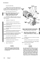
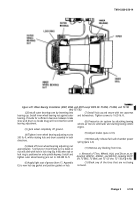
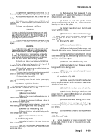
tire to ground, and tighten to 450-500 lb.-ft. using
sequence in figure 4-85. Jack up rude and position outer
wheel over inner stud nuts (fig. 4-84). Lower tire to
ground, and using sequence in figure 4-85, tighten nuts to
450-500 lb.-ft.
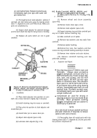
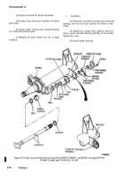
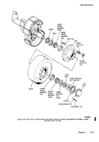
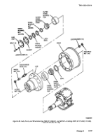
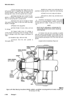
b. Removal of Tires, Wheels, Hub, and Drum as an
Assembly (M967, M969, and M970 except M970 SN
TC-0843, TC-0844, and TC-103 thru TC-178) (Fig. 4-86).
WARNING
The fall-safe chamber power spring must be
manually compressed and the air reservoirs
must be vented of pressure before removal of
hub and drum assembly.
(2) Manually compress fail-safe chamber power
spring (para 2-4).
(3) Release air pressure by opening drain wolves
on both air reservoirs (fig. 4-79).
(4) Jack up axle until tires are clear of ground.
Support rude with jack stand or blocking.
(5) Remove ten screws and lockwashers
(fig. 4-86) securing hub cap to hub. Remove hub cap and
hub cap gasket. Discard gasket.
(6) Remove outer wheel bearing nut (fig. 4-86),
leek ring, and inns wheel bring nut.
(7) Remove outer wheel bearing cone.
NOTE
If wheel lift jack is not available follow steps
(8) through (10).
(8) Apply grease (item 17, Appendix E) to a
45x20-inch 10 gage steel plate (table 4-1), laying a grease
track approximately lo-inches wide the length of the
plate.
(9) Place the grease plate, with greased side up,
under the tires. Lower tires so that they are just resting on
the grease plate, with the majority of the vehicle weight
still on the jack.
NOTE
It maybe necessary to back the automatic
adjusters out to allow brake shoes to dear
ridge on brake drum (para 4-33).
(10) Wide tires, wheels, hub, and brake drum off of
axle spindle.
(1) Block any of the tires that are not being
removed.
Change 3
4-101
Back to Top

