TM-9-2330-356-14
SEMITRAILER, TANK: 5000 GALLON, BULK HAUL, SELF LOAD/UNLOAD M967 AND M967A1; SEMITRAILER, TANK: 5000 GALLON, FUEL DISPENSING, AUTOMOTIVE M969 AND M969A1; SEMITRAILER, TANK: 5000 GALLON, FUEL DISPENSING, UNDER/OVERWING AIRCRAFT M970 AND M970A1
TECHNICAL MANUAL; OPERATOR’S, UNIT, DIRECT SUPPORT, AND GENERAL SUPPORT MAINTENANCE MANUAL
OCTOBER 1990
TM-9-2330-356-14 - Page 267 of 528
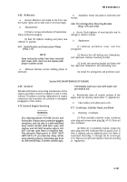
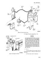
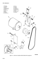
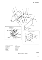
(3) Unscrew pipe plug (fig. 4-111) directly below
alternator from the intermediate housing.
(4) Remove bolt (3), lockwasher (2), and
flatwasher (1) securing alternator to adjusting bracket (4).
(5) Remove bolt (7), lockwasher (5), and nut (6),
then remove the adjusting bracket (4).
(6) Pull down on alternator to release tension on
alternator belt. Remove alternator belt from pulley.
(7) From underneath semitrailer, remove two
bolts (12 and 13), flatwashers (9), lockwashers (10), and
nuts (11).
(8) Remove ground cable (nearest) from
alternator.
(9) Pull alternator from mounting bracket (16).
Turn alternator and remove positive cable.
(10) Remove alternator.
b.
Adjustment of Alternator Drive Belt (Fig. 4-112).
(1) Loosen alternator adjusting bolt (3,
fig. 4-111) and mounting bolts (12 and 13) securing
alternator to mounting bracket (16).
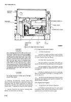
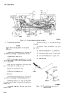
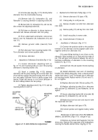
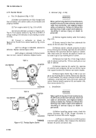
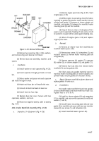
(2) Insert a crowbar (fig. 4-112) between
alternator and the pump housing. Be sure that lower end
of bar will bear against the pump housing. Pull UP on the
bar and apply sufficient force to obtain proper belt
tension. Proper belt tension is
1/8 to ¼-inch deflection in
the belt midway between the two pulleys.
(3) Tighten adjusting screw (3, fig. 4-111) and two
mounting bolts (12 and 13).
TA099852
Figure 4-112. Belt Deflection Adjustment.
TM 9-2330-356-14
c.
Replacement of Alternator Pulley (Fig. 4-111).
(1)
(2)
(3)
rotor shaft.
(4)
(5)
(6)
Remove alternator (19) (para 4-78).
Clamp pulley in a soft jaw vise.
Remove shoulder nut (20) from alternator
Remove pulley (17) and key from rotor shaft.
Install new pulley in reverse order.
Install alternator (19) (step
d).
d.
Installation of Alternator (Fig. 4-111).
(1) Connect the positive cable to the positive
terminal on the alternator and the negative cable to the
negative terminal on alternator (19).
(2) Locate sliding bushing in one of ears on the
alternator. Move bushing so it is flush with the inside of
ear. This will give more clearance between the ears to
facilitate installation of alternator to the mounting
bracket (16, fig. 4-111).
(3) Install bolt (13) and washer (9) into bushing
on alternator.
(4) Install alternator over ears of mounting
bracket (16). While doing this, have a second person
replace both bolts (12 and 13) through ears of alternator
and mounting bracket. Replace washers (10) and nuts (11).
Do not tighten.
(5) Replace alternator belt (18) over pulley (17).
(6) Replace adjusting bracket (4) on alternator
with capscrew (3), lockwasher (2), and flatwasher. Do not
tighten.
(7) Secure adjusting bracket (4) to bracket (8)
with capscrew (7), lockwasher (5), and nut (6).
(8) Replace buss bar box cover and secure it with
two capscrews and nuts.
(9) Adjust alternator belt (para 4-79).
(10) Connect positive and negative battery cables
to battery.
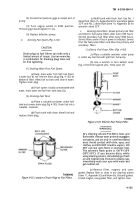
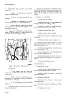
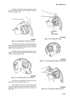
Replacement of Alternator Drive Belt (M967A1,
M969A1, and M970A1) (Figs. 4-113
through 4-122).
(1) Remove any broken belt fragments from the
drive area. Remove the capscrews and lockwashers
securing the flexible element drive ring (fig. 4-113).
4-131
Back to Top

