TM-9-2330-356-14
SEMITRAILER, TANK: 5000 GALLON, BULK HAUL, SELF LOAD/UNLOAD M967 AND M967A1; SEMITRAILER, TANK: 5000 GALLON, FUEL DISPENSING, AUTOMOTIVE M969 AND M969A1; SEMITRAILER, TANK: 5000 GALLON, FUEL DISPENSING, UNDER/OVERWING AIRCRAFT M970 AND M970A1
TECHNICAL MANUAL; OPERATOR’S, UNIT, DIRECT SUPPORT, AND GENERAL SUPPORT MAINTENANCE MANUAL
OCTOBER 1990
TM-9-2330-356-14 - Page 272 of 528
TM 9-2330-356-14
(b)
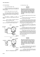
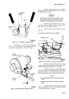
The clearance should be between
0.070-inch and 0.120-inch (as near to 0.070-inch as
possible).
(c)
Adjust the link screw on the end of the
solenoid plunger for proper clearance.
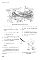
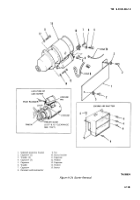
(2) Raise engine air shutter and position the
starter motor and shield on engine. Install top retaining
capscrew (11) and washer (12) on starter. Using a 3/8-inch
drive set, long extension, universal joint, and a 9/16-inch
universal socket, install bottom starter capscrew (13) and
washer (14).
(3) Secure starter support bracket to starter
using capscrew (7), washer (8), and nut (9). Do not tighten.
(4) Using capscrew (5) and washer (6) secure
starter support bracket to engine. Tighten capscrew (7),
washer (8), and nut (9).
solenoid.
shutter.
(fig, 4-37).
(5)
Attach leads No. 74 and No. 6 to starter
(6)
Replace the five capscrews (4) on engine air
(7)
Connect negative battery cable to battery
4-80. Starter Solenoid
WARNING
When performing electrical maintenance,
ALWAYS disconnect intervehicular electrical
cable from semitrailer, and negative battery
cables at batteries. Failure to follow this
warning may create a spark and explosion,
resulting in serious injury or death to
personnel.
a.
Removal.
(1) Remove negative battery cable from battery
(fig. 4-37).
(2) Starter solenoid removal must be done from
underneath the vehicle on the left side of the engine.
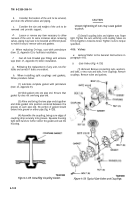
(3) Remove starter solenoid protective bracket
(1) by removing the two retaining capscrews (2) and
washers (3).
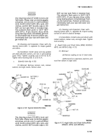
(4) Remove hot lead No. 6 from large bottom
pole of solenoid and lead No. 74 from small pole.
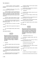
(5) Remove linkage pin which connects solenoid
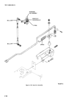
shaft to linkage (fig. 4-124).
(6) Remove two screws that fasten solenoid to
starter motor. Remove solenoid.
b.
Installation.
(1) Position starter solenoid on starter motor and
fasten with two screws.
(2) Connect starter linkage to solenoid using
linkage pin.
(3) Attach hot lead No. 6 to large bottom pole of
solenoid and lead No. 74 to small pole.
(4) Replace starter solenoid protective shield.
Fasten with two capscrews and washers.
(5) Connect negative battery cable to battery
(fig. 4-37).
4-81. Buss Bar
WARNING
When performing electrical maintenance,
ALWAYS disconnect intervehicular electrical
cable from semitrailer, and negative battery
cables at batteries. Failure to follow this
warning may create a spark and explosion,
resulting in serious injury or death to
personnel.
a.
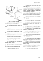
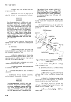
Replacing Buss Fuse (Fig. 4-125).
(1) Disconnect negative battery cable from
battery (fig. 4-37).
(2) Remove buss bar cover (fig. 4-125) by
removing two capscrews and nuts.
(3) Remove buss bar fuse from its clips.
(4) Install new fuse between clips.
(5) Replace buss bar cover. Attach to firewall
with two capscrews and nuts.
(6) Reconnect negative battery cable to battery
(fig. 4-37).
b.
Removal.
(1) Perform steps (1) through (3) of paragraph
a.
(2) Disconnect all electrical leads from buss bar.
4-136
Back to Top

