TM-9-2330-356-14
SEMITRAILER, TANK: 5000 GALLON, BULK HAUL, SELF LOAD/UNLOAD M967 AND M967A1; SEMITRAILER, TANK: 5000 GALLON, FUEL DISPENSING, AUTOMOTIVE M969 AND M969A1; SEMITRAILER, TANK: 5000 GALLON, FUEL DISPENSING, UNDER/OVERWING AIRCRAFT M970 AND M970A1
TECHNICAL MANUAL; OPERATOR’S, UNIT, DIRECT SUPPORT, AND GENERAL SUPPORT MAINTENANCE MANUAL
OCTOBER 1990
TM-9-2330-356-14 - Page 275 of 528
TM 9-2330-356-14
Section XVIII. MAINTENANCE OF FILTER/SEPARATOR AND SUMP COMPONENTS
(M969, M969A1, M970, and M970A1)
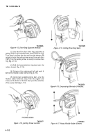
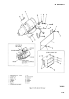
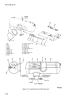
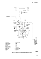
4-83. Filter/Separator (Fig. 4-127)
WARNING
Read and observe all safety precautions
listed in the Warning Summary before
performing maintenance on filter/separator.
Ensure that semitrailer is grounded to an
approved (earth) ground and it is safe to
proceed. Failure to follow this warning may
cause a spark to ignite, resulting in serious
injury or death to personnel.
a.
Removal of Elements and Fuses.
NOTE
Be sure all valves are closed.
(1) Place a suitable container under the manual
drain valve N (fig. 4-127). Open valve N and remove any
fluid from filter/separator. When thoroughly drained,
close drain valve.
NOTE
Note location of lead seal wires for
installation.
(2) Cut two lead seal wires at top and bottom of
cover (4).
(3) Remove 12 nuts (1), bolts (2), and washers (3)
that fasten cover (4) to mounting flange.
(4) Remove cover (4) by pulling straight out from
flange.
(5) Remove gasket (5) and discard.
(6) Unscrew four wingnuts (6) and remove with
washers (7 and 8).
(7) Remove retaining plate (9).
(8) Starting with lower canister assembly
(nearest to service port), remove the support (10), and pull
canister assembly (11) to the right until it drops down so it
can be removed through the service port.
(9) Remove the four remaining canister
assemblies in the same way; always remove lower canister
assembly first.
(10) Disassemble canister assembly as follows:
(a)
Pull adapter (13) from canister (12).
(b)
Remove fuses (15) from canister and
discard.
(c)
Remove fuse clip (14).
(d)
Remove two gaskets (16 and 17) from
adapter. Gasket (17) might remain in filter/separator;
remove it.
(11) Unscrew plastic retainers (18) from the
element (19) guide pipes.
(12) Slide elements (19) off guide pipes.
b.
Installation of Elements and Fuses.
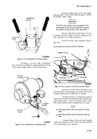
(1) Start installation of elements (19, fig. 4-127)
on the guide pipes farthest from the service port. Coat
O-ring of element with petrolatum (item 23, Appendix E).
Install elements on guide pipes.
(2) Install plastic retainers (18) and hand tighten
only. Do not overtighten.
(3) Reassemble canister assembly:
(a)
Install two new gaskets (16 and 17) in
adapter (13). Gasket (16) will not go in flat.
(b)
Place adapter on bench and insert three
new Go-No-Go fuses (15). Push fuses all the way down
into holes.
(c)
Place clip (14) on top of fuses.
(d)
Slide canister (12) over fuses (15) and
push into adapter.
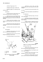
(4) Put a canister assembly through the service
port with adapter end down toward bottom of tank. Turn
adapter end to the left and lift canister into position on the
upper guide rods farthest from service port. Slide canister
to the left until it fits into the outlet hole.
(5) Raise end of canister assembly and install
support (10) near end of canister.
(6) Install next canister on top guide rods,
followed by lower row starting with the farthest
installation and working toward service port.
NOTE
Hand tighten wingnuts. DO NOT use a
wrench.
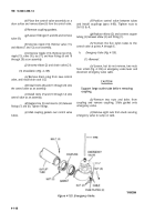
(7) Replace canister retainer plate (9) and secure
with four wingnuts (6) and washers (7 and 8).
4-139
Back to Top

