TM-9-2330-356-14
SEMITRAILER, TANK: 5000 GALLON, BULK HAUL, SELF LOAD/UNLOAD M967 AND M967A1; SEMITRAILER, TANK: 5000 GALLON, FUEL DISPENSING, AUTOMOTIVE M969 AND M969A1; SEMITRAILER, TANK: 5000 GALLON, FUEL DISPENSING, UNDER/OVERWING AIRCRAFT M970 AND M970A1
TECHNICAL MANUAL; OPERATOR’S, UNIT, DIRECT SUPPORT, AND GENERAL SUPPORT MAINTENANCE MANUAL
OCTOBER 1990
TM-9-2330-356-14 - Page 277 of 528
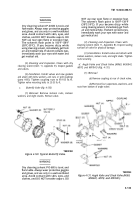
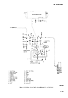
(8) Install new gasket (5).
(9) Replace cover (4). Secure with twelve bolts
(2), washers (3), and nuts (1). Ensure that four bolts with
holes in shaft are installed where lead seal wires will be
installed.
(10) Install one lead seal wire through holes in top
pair of bolts (2) and one through holes in bottom pair. Put
wires through seals and crimp, using tool, Lead Seal Press,
NSN 5120-00-224-7592. Trim excess wire.
4-84. Sump Components
WARNING
Read and observe all safety precautions
listed in the Warning Summary before per-
forming maintenance on sump components.
Ensure that semitrailer is grounded to an ap-
proved (earth) ground and it is safe to pro-
ceed. Failure to follow this warning may
cause a spark to ignite, resulting in serious in-
jury or death to personnel.
a.
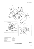
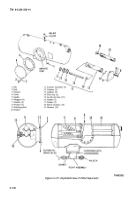
Automatic Drain Valve and Float Assembly.
(1)
Removal.
(a)
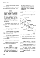
Close valve M.
(b)
Place a suitable container under the
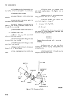
manual drain valve N (fig. 4-127). Open valve N and
remove air fluid from filter/separator. When thoroughly
drained, close valve N.
NOTE
DO NOT disconnect the tubes connecting the
float assembly to the automatic drain valve.
(c)
Disconnect the tube coming from top of
filter/separator at the float assembly. Only the M970 and
M970A1 have a second tube to be disconnected.
assembly.
(e)
(f)
assembly.
TM 9-2330-356-14
(d)
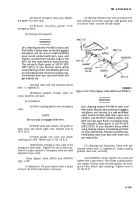
Remove the eight capscrews and
washers that fasten the float assembly to the
filter/separator. Remove float and automatic drain valve
Remove and discard gasket.
Remove manual drain valve from the
(2)
Installation.
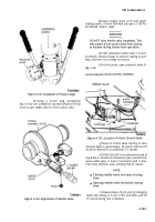
(a)
Place a new gasket on flange of float
assembly.
(b)
Install float and automatic drain valve to
filter/separator. Attach with eight capscrews and washers.
Tighten securely.
(c)
Connect the tube line(s) to the float
assembly.
b.
Replacement of Manual Drain Valve.
(1) Close valve M.
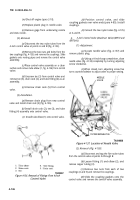
(2) Place a suitable container under the manual
drain valve N (fig. 4-127). Open valve N and remove all
fluid from filter/separator.
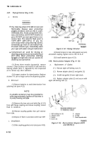
(3) Unscrew manual drain valve from float
assembly. Be sure nipple does not come off with drain
valve.
NOTE
Be sure manual drain valve is closed.
(4) Screw manual drain valve tightly onto nipple
of float assembly.
Section XIX. MAINTENANCE OF DISPENSING EQUIPMENT
4-85. General
ment. Ensure that semitrailer is grounded to
an approved (earth) ground and it is safe to
proceed. Failure to follow this warning may
WARNING
cause a spark to ignite, resulting in serious in-
jury or death to personnel.
Read and observe all safety precautions
listed in the Warning Summary before per-
a.
Read and observe all safety precautions in the
forming maintenance on dispensing equip-
Warning Summary.
4-141
Back to Top

