TM-9-2330-356-14
SEMITRAILER, TANK: 5000 GALLON, BULK HAUL, SELF LOAD/UNLOAD M967 AND M967A1; SEMITRAILER, TANK: 5000 GALLON, FUEL DISPENSING, AUTOMOTIVE M969 AND M969A1; SEMITRAILER, TANK: 5000 GALLON, FUEL DISPENSING, UNDER/OVERWING AIRCRAFT M970 AND M970A1
TECHNICAL MANUAL; OPERATOR’S, UNIT, DIRECT SUPPORT, AND GENERAL SUPPORT MAINTENANCE MANUAL
OCTOBER 1990
TM-9-2330-356-14 - Page 281 of 528
TM 9-2330-356-14
TA099863
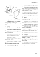
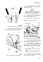
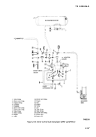
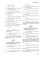
Figure 4-133. Installation of Pressure Gage.
(f)
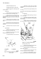
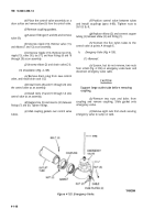
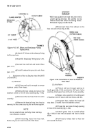
Using a 4-inch long screwdriver
(fig. 4-134), turn screwdriver counterclockwise 8-10 full
turns to open needle valve on 4-inch control valve.
(g)
Start engine (para 2-10) and begin
loading (para 2-14a for self-load and para 2-13b for
non-filtered bottom load).
WARNING
DO NOT close needle valve completely. This
will prevent 4-inch control valve from closing
at anytime during bottom load operations.
(h)
Close (clockwise) needle valve in ¼-turn
increments. Observe change in pressure reading at each
step, until there is no change in pressure.
(i)
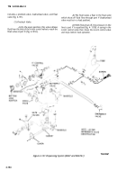
At this point, open precheck valve D
(fig. 2-26).
TA099866
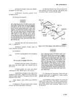
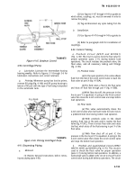
Figure 4-135. Location of 4-Inch Control Valve.
Figure 4-134. Adjustment of Needle Valve.
TA099864
(j)
Sound of control valve starting to close
should be heard in approximately
30 seconds. Full shut off
should be obtained in an additional 3–5 seconds.
(k)
If full shut off is not obtained (sound of
liquid flow or whistle are indications) open (counterclock-
wise) needle valve in ¼-turn increments until it does.
Then close precheck valve, allowing flow to resume.
NOTE
Closing needle valve increases closing
time.
Opening needle valve decreases closing
time.
(1) Repeat steps
(h), (i),
and
(j),
changing
needle valve setting in ¼-turn or less increments until the
3-5 second closing rate is obtained.
4-145
Back to Top

