TM-9-2330-356-14
SEMITRAILER, TANK: 5000 GALLON, BULK HAUL, SELF LOAD/UNLOAD M967 AND M967A1; SEMITRAILER, TANK: 5000 GALLON, FUEL DISPENSING, AUTOMOTIVE M969 AND M969A1; SEMITRAILER, TANK: 5000 GALLON, FUEL DISPENSING, UNDER/OVERWING AIRCRAFT M970 AND M970A1
TECHNICAL MANUAL; OPERATOR’S, UNIT, DIRECT SUPPORT, AND GENERAL SUPPORT MAINTENANCE MANUAL
OCTOBER 1990
TM-9-2330-356-14 - Page 289 of 528
TM 9-2330-356-14
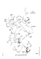
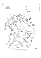
(2) Use figures 4-147 through 4-149 as guides to
which valves, couplings, etc. must be removed in order to
remove the piping.
b.
Installation.
(3) Tag and disconnect any nylon tubing from the
(1) Use figures 4-147 through 4-149 as guides to
(2) Refer to paragraph 4-85 for installation of
couplings.
4-92. Control Tubing
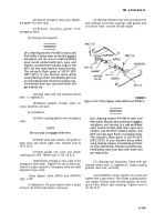
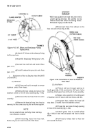
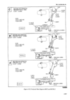
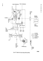
a. Precheck Circuit (M970 and M970A1)
TA099875
(Fig.
4-150). The
circuit is used to check the float valve for
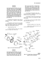
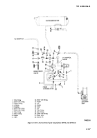
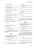
Figure 4-145. Deadman Control.
proper operation (para 2-11) during bottom load
operations. The circuit includes the precheck valve, the
4-90. Centrifugal Pump
float valve, and all necessary tubing and fittings
(fig. 4-150).
a.
Lubrication.
Lubricate the intermediate housing
(1)
Precheck Valve.
bearing weekly. Refer to figures 3-1 through 3-6 for
lubrication instructions and correct lubricant.
(a)
In the open position, this valve allows
fluid from the inlet of the 4-inch control valve to reach the
b.
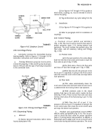
Priming.
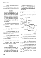
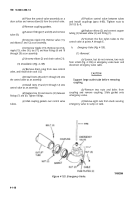
Whenever pump has lost its prime,
float valve at port X (fig. 4-150A).
remove fill plug (fig. 4-146) and fill pump housing to
bottom of fill port with the type of fuel being transported
(b)
The fluid raises a float in the float valve
in the semitrailer tank.
and shuts off fluid flow through port Y (fig. 4-150B).
(c)
With flow shut off, the pressure in the
line to port Y is equalized. A spring in the 4-inch control
valve then closes the 4-inch control valve and stops bottom
load operations.
(2)
Float Valve.
(a)
This valve automatically closes the
4-inch control valve when fuel level inside the tank rises to
a predetermined level during bottom load operation.
(b)
With precheck valve in the closed
position, fluid rises in the tank until it reaches the float
valve (fig. 4-150C). There it enters float valve and raises
the float, which shuts off the fluid entering in port Y of the
float valve.
(c)
With flow shut off at port Y, the
pressure in the line to port Y is equalized. A spring in the
TA099876
4-inch control valve then closes the 4-inch control valve
Figure 4-146. Priming Centrifugal Pump.
and stops the bottom load operation.
4-91. Dispensing Piping
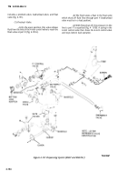
b.
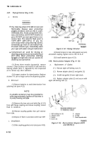
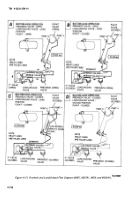
Precheck and Load/Unload Circuit (M967,
M967A1, M969, and M969A1) (Fig. 4-151).
This circuit is
a.
Removal.
used to check the float valve for proper operation
(para 2-11) during bottom load operations. In addition, a
(1) Review General Instructions before remov-
load/unload valve is added to the circuit to shut off 4-inch
ing any piping (para 4-85).
control valve during bulk delivery operations. The circuit
4-153
Back to Top

