TM-9-2330-356-14
SEMITRAILER, TANK: 5000 GALLON, BULK HAUL, SELF LOAD/UNLOAD M967 AND M967A1; SEMITRAILER, TANK: 5000 GALLON, FUEL DISPENSING, AUTOMOTIVE M969 AND M969A1; SEMITRAILER, TANK: 5000 GALLON, FUEL DISPENSING, UNDER/OVERWING AIRCRAFT M970 AND M970A1
TECHNICAL MANUAL; OPERATOR’S, UNIT, DIRECT SUPPORT, AND GENERAL SUPPORT MAINTENANCE MANUAL
OCTOBER 1990
TM-9-2330-356-14 - Page 295 of 528
TM 9-2330-356-14
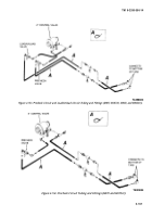
(2)
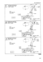
Float Valve.
secondary air reservoir to operate a normally closed pilot
valve A on the 3-inch control valve.
(a)
This valve automatically closes the
4-inch control valve when fuel level inside tank rises to a
predetermined level during bottom load operation.
(b)
With precheck valve in the closed
position, fluid rises in the tank until it reaches the float
valve (fig. 4-151C).
(c)
There it enters float valve and raises the
float which shuts off the fluid entering in port Y of the
float valve (load/unload valve must be in load position).
(d)
With flow shut off at port Y the pressure
in the line to port Y is equalized. A spring in the 4-inch
control valve then closes the 4-inch control valve and stops
the bottom load operation.
(3)
Load/Unload Valve.
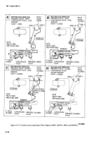
(a)
Unlike the M970 and M970A1, the
M967, M967A1, M969, and M969A1 do not provide a
means to manually shut down flow to the 4-inch control
valve during bulk delivery operations.
(b)
During these operations, fuel exiting the
pump will follow two paths; one to either the piping
control or the filter/separator (dependent on operation)
and the other to the 4-inch control valve.
(c)
When the fuel reaches the 4-inch
control valve inlet, the valve opens and allows fuel to
follow a path back to the pump. Consequently, the pump
actually recirculates the fuel in the piping system.
Therefore, when performing bulk delivery operations, the
load/unload valve is switched to the unload position. This
closes the load/unload valve and disrupts the flow in the
line to port Y on the float valve before it reaches the float
(fig. 4-151D).
(d)
Because the load/unload valve is
connected in series in the line to port Y, when precheck
operation or loading operations are performed, the
load/unload valve must be in the load (open) position
(fig. 4-151A and 4-151B).
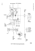
c.
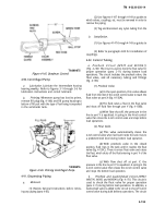
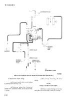
Deadman Control Circuit (M970 and M970A1)
(Fig. 4-152).
(1) When the underwing nozzle is used in
conjunction with the 2½-inch hose reel, the deadman
control is used to control the fuel flow through the
underwing nozzle.
(2) The deadman control S (fig. 4-152) is a
hand-held control which uses air pressure from the
(3) When the normally closed pilot valve A is
closed, fuel from the inlet side of the 3-inch control passes
through a needle valve and into the 3-inch control valve
spring chamber. It also passes through normally open pilot
valves B and C on its way to the manifold.
(4) Fuel also flows through the 3-inch control to
the 2½-inch hose reel.
(5) As it enters the hose reels, fuel is bled off
through a pilot line, through the check valve portion of
deadman release valve, to the normally-open pilot valve
B.
(6) The fuel pressure closes pilot valve B,
creating pressure in the spring chamber of the 3-inch
control valve. The additional pressure created on the
valve poppet of the 3-inch control valve closes the valve,
stopping flow to the underwing nozzle.
(7) To open the control valve, the trigger on the
deadman control is squeezed, and air from the secondary
air reservoir is directed to the normally-closed pilot valve
A to open the pilot valve.
(8) Once Valve A is open, the pressure in the
spring chamber of the 3-inch control valve is relieved and
the control valve opens.
(9) When the water level in the filter/separator
sump is high enough to raise the float in the automatic
drain valve, pilot pressure is sent through the pilot line
from the automatic drain valve to the pilot valve C.
(10) The pilot valve C closes, creating pressure in
the spring chamber of the 3-inch control valve.
(11) The additional pressure created on the valve
poppet of the 3-inch control valve closes the valve,
stopping flow to the underwing nozzle.
(12) When water is drained from the
filter/separator, the float lowers and shuts off the pressure
to the pilot valve C. Pilot valve C opens and flow through
the 3-inch control valve continues.
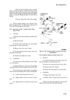
d.
Removal of Control Tubing.
(1)
General.
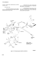
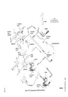
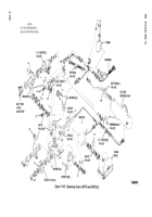
The general arrangement of the
control tubing is shown in figures 4-153 through 4-155. The
control tubing is nylon and is fastened in various locations
with straps.
4-159
Back to Top

