TM-9-2330-356-14
SEMITRAILER, TANK: 5000 GALLON, BULK HAUL, SELF LOAD/UNLOAD M967 AND M967A1; SEMITRAILER, TANK: 5000 GALLON, FUEL DISPENSING, AUTOMOTIVE M969 AND M969A1; SEMITRAILER, TANK: 5000 GALLON, FUEL DISPENSING, UNDER/OVERWING AIRCRAFT M970 AND M970A1
TECHNICAL MANUAL; OPERATOR’S, UNIT, DIRECT SUPPORT, AND GENERAL SUPPORT MAINTENANCE MANUAL
OCTOBER 1990
TM-9-2330-356-14 - Page 280 of 528
TM 9-2330-356-14
(c)
Remove angle valve and check valve as a
complete assembly.
(d)
Separate check valve and angle valve on
a bench by removing four capscrews, washers, and nuts.
WARNING
Dry cleaning solvent P-D-680 is toxic and
flammable. Always wear protective goggles
and gloves, and use only in a well-ventilated
area. Avoid contact with skin, eyes, and
clothes, and DO NOT breathe vapors. DO
NOT use near open flame or excessive heat.
The solvent’s flash point is 100°F-138°F
(38°C-59°C). If you become dizzy while
using cleaning solvent, immediately get fresh
air and medical help. If solvent contacts eyes,
immediately wash your eyes with water and
get medical aid.
(2)
Cleaning and Inspection.
Clean with dry
cleaning solvent (item 11, Appendix E). Inspect gaskets
and valves.
(3)
Installation.
(a)
Assemble angle valve, new gasket, and
check valve assembly by securing both valves together with
four capscrews, washers, and nuts.
(b)
Position angle valve and check valve
between manifold and pipe. Install new gasket, four
capscrews, washers, and nuts to secure angle valve to
manifold. Do not tighten capscrews.
(c)
Install coupling and gasket (para 4-85h).
Tighten coupling nuts to 57-63 lb.-ft.
(d)
Tighten capserews securing angle valve
to manifold to 25-35 lb.-ft.
e.
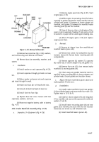
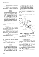
Check Valve (M967, M967A1, M969, and M969A1)
(Fig. 4-132) .
(1)
Removal.
Remove sixteen capscrews,
washers, and nuts. Remove valve and gaskets.
WARNING
Dry cleaning solvent P-D-680 is toxic and
flammable. Always wear protective goggles
and gloves, and use only in a well-ventilated
area. Avoid contact with skin, eyes, and
clothes, and DO NOT breathe vapors. DO
NOT use near open flame or excessive heat.
The solvent’s flash point is 100°F-138°F
(38°C-59°C). If you become dizzy while
using cleaning solvent, immediately get fresh
air and medical help. If solvent contacts eyes,
immediately wash your eyes with water and
get medical aid.
(2)
Cleaning and Inspection.
Clean with dry
cleaning solvent (item 11, Appendix E). Inspect gaskets
and valves.
(3)
Installation.
Install valve and new gaskets with
sixteen capserews, washers, and nuts. Tighten nuts to
25-35 lb.-ft.
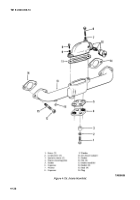
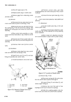
Figure 4-132. Check Valve (M967, M967A1, M969,
and M969A1).
f.
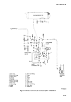
4-Inch Control Valve (Bottom Loading)
(Figs. 4-134 and 4-135).
TA099862
(1)
Adjustment (to ensure that fuel shut-off closes).
(a)
Start with empty tank.
(b)
Refer to flow diagram for either filtered
self-load (fig. 2-34) or non-filtered bottom load
(fig. 2-22).
(c)
Install a 0-60 psi pressure gage in the
3/8-inch NPT port on underwing nozzle (fig. 4-133) for
filtered self-load or non-filtered bottom load.
(d)
Connect underwing nozzle (for
self-load) or storage facility hose to the bottom load
adapter (figs. 4-147 through 4-149).
(e)
Remove plastic plug (fig. 4-134) from
needle
valve.
4-144
Back to Top

