TM-9-2330-356-14
SEMITRAILER, TANK: 5000 GALLON, BULK HAUL, SELF LOAD/UNLOAD M967 AND M967A1; SEMITRAILER, TANK: 5000 GALLON, FUEL DISPENSING, AUTOMOTIVE M969 AND M969A1; SEMITRAILER, TANK: 5000 GALLON, FUEL DISPENSING, UNDER/OVERWING AIRCRAFT M970 AND M970A1
TECHNICAL MANUAL; OPERATOR’S, UNIT, DIRECT SUPPORT, AND GENERAL SUPPORT MAINTENANCE MANUAL
OCTOBER 1990
TM-9-2330-356-14 - Page 284 of 528
TM 9-2330-356-14
(e)
Place the control valve assembly on a
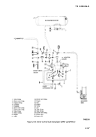
clean surface and remove elbow (6) from the control valve.
(f)
Remove coupling gaskets.
(g)
Loosen fittings (7) and (8) and remove
tube (9).
(h)
Unscrew nipple (10). Remove valve (11),
and elbows (7 and 12) as an assembly.
(i)
Unscrew nipple (13). Remove tee (14),
nipple (15), valve (16), tee (17), and hose fittings (8 and 18
through 20) as an assembly.
(j)
Unscrew elbow (2) and drain valve (21).
(3)
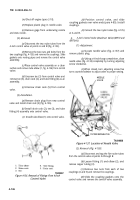
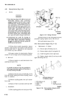
Installation (Fig. 4-138).
(a)
Remove drain plug from new control
valve, and install drain cock (12).
(b)
Install items (8) and (13 through 20) onto
the control valve as an assembly.
(c)
Install items (7) and (10 through 12) onto
control valve as an assembly.
(d)
Replace line (9) and inserts (22) between
fittings (7) and (8). Tighten fittings.
(e) Slide
coupling gaskets over control valve
tubes.
(f)
Position control valve between tubes
and install couplings (para 4-85). Tighten nuts to
95-105 lb.-ft.
(g)
Replace elbow (2) and connect copper
tubing (3) between elbow (2) and fitting (1).
(h)
Connect the five nylon tubes to the
control valve at points A through E.
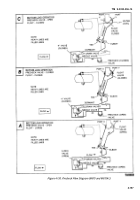
h.
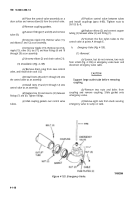
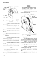
Emergency Valve (Fig. 4-139).
(1)
Removal.
(a)
Loosen, but do not remove, two nuts
from U-bolt (fig. 4-139) on emergency valve lever and
disconnect emergency valve cable.
CAUTION
Support large outlet tube before removing
coupling.
(b)
Remove two nuts and bolts from
coupling and remove coupling. Slide gasket onto
emergency valve.
(c)
Remove eight nuts from studs securing
emergency valve to sump on tank.
Figure 4-139. Emergency Valve.
TA502366
4-148
Back to Top

