TM-9-2330-356-14
SEMITRAILER, TANK: 5000 GALLON, BULK HAUL, SELF LOAD/UNLOAD M967 AND M967A1; SEMITRAILER, TANK: 5000 GALLON, FUEL DISPENSING, AUTOMOTIVE M969 AND M969A1; SEMITRAILER, TANK: 5000 GALLON, FUEL DISPENSING, UNDER/OVERWING AIRCRAFT M970 AND M970A1
TECHNICAL MANUAL; OPERATOR’S, UNIT, DIRECT SUPPORT, AND GENERAL SUPPORT MAINTENANCE MANUAL
OCTOBER 1990
TM-9-2330-356-14 - Page 278 of 528
TM 9-2330-356-14
b.
Consider the location of the unit to be serviced,
and drain the affected valves and piping.
c.
Consider the size and weight of the unit to be
removed and provide support.
d.
Loosen or remove any item necessary to allow
removal of the unit. In some instances when removing
valves, piping may have to be loosened at different places
to make it easy to remove valve and gaskets.
e.
When replacing O-rings, coat with petrolatum
(item 23, Appendix E) to facilitate installation.
f.
Coat all male threaded pipe fittings with antiseize
tape (item 27, Appendix E) before installation.
g.
Following the replacement of any unit, test for
leaks and correct if leaks are evident.
h.
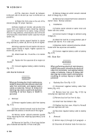
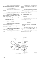
When installing split couplings and gaskets,
follow procedure below:
(1) Lubricate complete gasket with petrolatum
(item 23, Appendix E).
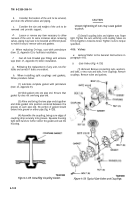
(2) Slide gasket onto one pipe end. Ensure that
gasket lip does not overhang pipe end.
(3) Aline and bring the two pipe ends together
and slide gasket into position centered between the
grooves on each pipe end. No portion of gasket should
extend into groove on either pipe (fig. 4-128).
(4) Assemble the coupling, being sure edges of
coupling drop securely into grooves. Squeeze housing
tight with hands to further center the gasket and seat the
housing.
TA502383
Figure 4-128. Installing Coupling Gasket.
CAUTION
Uneven tightening of nuts may cause gasket
to pinch.
(5) Install coupling bolts and tighten nuts finger
tight. Tighten the nuts uniformly until coupling halves are
firmly together–metal-to-metal. Tighten nuts to torque
specified.
4-86. Valves
a.
General.
Refer to the General Instructions in
paragraph 4-85.
b.
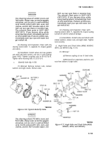
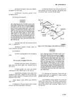
Gate Valves (Fig. 4-129).
(1)
Removal.
Remove connecting nuts, washers,
and bolts, or two nuts and bolts, from couplings. Remove
couplings. Remove valve and gaskets.
Figure 4-129. Typical Gate Valves and Couplings.
TA099859
4-142
Back to Top

