TM-9-2330-356-14
SEMITRAILER, TANK: 5000 GALLON, BULK HAUL, SELF LOAD/UNLOAD M967 AND M967A1; SEMITRAILER, TANK: 5000 GALLON, FUEL DISPENSING, AUTOMOTIVE M969 AND M969A1; SEMITRAILER, TANK: 5000 GALLON, FUEL DISPENSING, UNDER/OVERWING AIRCRAFT M970 AND M970A1
TECHNICAL MANUAL; OPERATOR’S, UNIT, DIRECT SUPPORT, AND GENERAL SUPPORT MAINTENANCE MANUAL
OCTOBER 1990
TM-9-2330-356-14 - Page 269 of 528
TM 9-2330-356-14
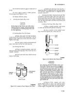
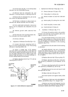
(6) After the belt has been maneuvered around
the flexible rubber element, pull it through the inside of
the drive ring (fig. 4-118).
TA222981
Figure 4-118. Pulling Belt Through Drive Ring.
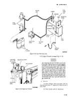
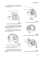
(7) Aline the drive ring non-threaded mounting
holes with the threaded flywheel holes and engage the
capscrews with lockwashers finger tight. Do not fully
tighten at this time (fig. 4-120).
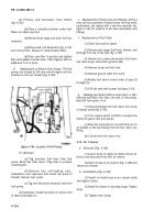
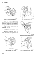
(8) Slide the drive ring back into position on the
flexible rubber element and pull the belt into the drive
sheave “V” groove (fig. 4-119).
TA222982
Figure 4-119. Positioning Belt on Drive Sheave.
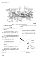
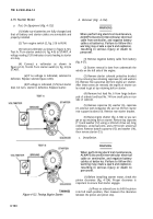
(9) Check the arrangement of the drive belt for
alinement with the alternator (fig. 4-121).
(10) Retighten the drive ring capscrews with
lockwashers evenly in an alternating pattern. Tighten the
capscrews with lockwashers to 10.5 lb.-ft. (126 lb.-in.)
(fig. 4-122).
TA222983
Figure 4-120. Alining Drive Ring.
TA222984
Figure 4-121. Checking Belt and Alternator Alinement.
TA222985
Figure 4-122. Torquing Drive Ring Capscrews.
4-133
Back to Top

