TM-9-2330-356-14
SEMITRAILER, TANK: 5000 GALLON, BULK HAUL, SELF LOAD/UNLOAD M967 AND M967A1; SEMITRAILER, TANK: 5000 GALLON, FUEL DISPENSING, AUTOMOTIVE M969 AND M969A1; SEMITRAILER, TANK: 5000 GALLON, FUEL DISPENSING, UNDER/OVERWING AIRCRAFT M970 AND M970A1
TECHNICAL MANUAL; OPERATOR’S, UNIT, DIRECT SUPPORT, AND GENERAL SUPPORT MAINTENANCE MANUAL
OCTOBER 1990
TM-9-2330-356-14 - Page 263 of 528
TM 9-2330-356-14
d.
Installation.
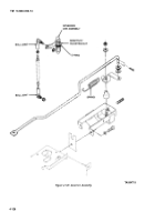
(1) Remove screw, handle, packing nut, one nut,
and washer from handle end of cable.
(2) On opposite end remove one jam nut.
(3) Install cable through channel of control
panel. Replace the jam nut, packing nut, handle, and
screw.
(4) Thread cable through hole in engine
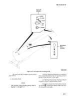
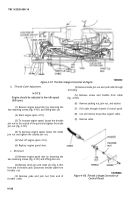
shrouding. Replace inside jam nut (fig. 4-107), but do not
tighten.
(5) Replace jam nut and yoke and attach yoke to
throttle rod with clevis pin and cotter pin.
(6)
(7)
(step
b).
(8)
(9)
Start engine (para 2-10).
Adjust engine speed to low idle (900 rpm)
Shut off engine (para 2-10).
Replace engine cover panel.
(10) Replace straps.
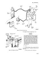
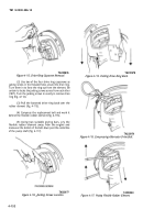
4-76. Governor Assembly (Fig. 4-109)
a.
Service.
WARNING
Dry cleaning solvent P-D-680 is toxic and
flammable. Always wear protective goggles
and gloves, and use only in a well-ventilated
area. Avoid contact with skin, eyes, and
clothes, and DO NOT breathe vapors. DO
NOT use near open flame or excessive heat.
The solvent’s flash point is 100°F-138°F
(38°C-59°C). If you become dizzy while
using cleaning solvent, immediately get fresh
air and medical help. If solvent contacts eyes,
immediately wash your eyes with water and
get medical aid.
(1) Clean all accessible linkage with dry cleaning
solvent (item 11, Appendix E). Wipe dry with a clean cloth.
(2) Periodically lubricate the ball joints
(fig. 4-109) with OE-10 oil (item 21, Appendix E).
Remove the engine panel door (fig. 4-101) to gain access
to the ball joints.
b.
Governor Sensitivity Adjustment (No Engine Surge).
(1) Start engine (para 2-10).
(2) Locate access hole cover on side of engine
blower housing and remove cover (fig. 4-101).
(3) Locate the governor arm assembly
(fig. 4-109).
(4) For a coarse adjustment, relocate the spring
in the notches in the governor arm.
(5) For a fine adjustment, insert a screwdriver
through the access hole to ratchet-type base of the
governor arm. Turn the ratchet hub clockwise to decrease
sensitivity or counterclockwise to increase sensitivity.
(6) Adjust for maximum sensitivity without a
surging condition.
(7) Stop engine (para 2-10).
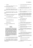
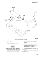
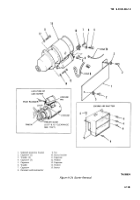
4-77. Engine Muffler/Exhaust
a.
Removal (Fig. 4-110).
(1) Remove muffler shroud by removing ten
capscrews that secure shroud to panels (fig. 4-101).
(2) Loosen clamp (fig. 4-110) on the exhaust
pipe by loosening a bolt and a nut.
(3) Remove two muffler clamps securing muffler
to mounting plate. Remove muffler.
(4) Remove two capscrews and lockwashers from
the exhaust pipe at the manifold. Remove exhaust pipe
adapter and gasket.
b.
Installation (Fig. 4-110).
(1) Install a new gasket between exhaust pipe and
exhaust manifold. Secure exhaust pipe and adapter to
manifold with two capscrews and lockwashers.
(2) Put exhaust pipe clamp over end of exhaust
pipe and insert muffler inlet into exhaust pipe. Do not
tighten clamp.
(3) Replace muffler clamps and tighten.
(4) Tighten exhaust pipe clamp.
(5) Replace muffler shroud, securing with ten
capscrews (fig. 4-101).
4-127
Back to Top

